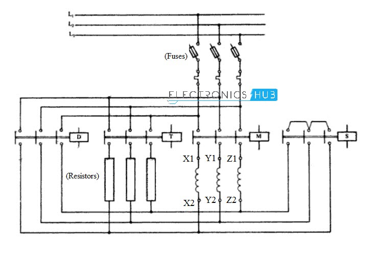
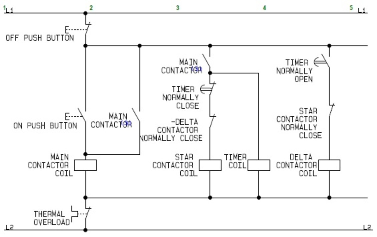
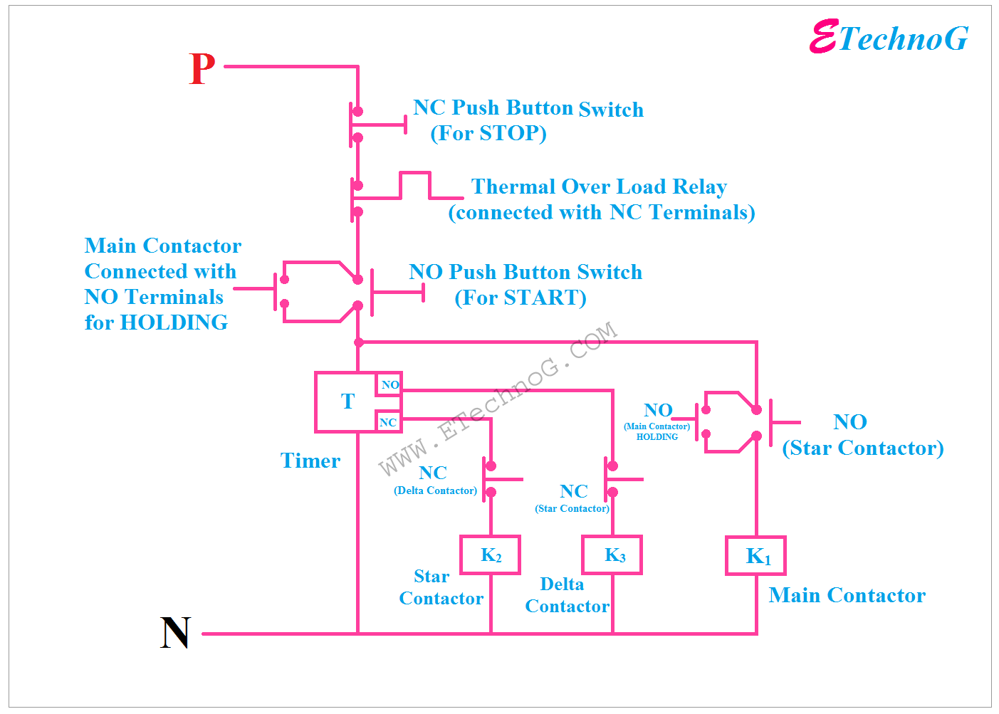
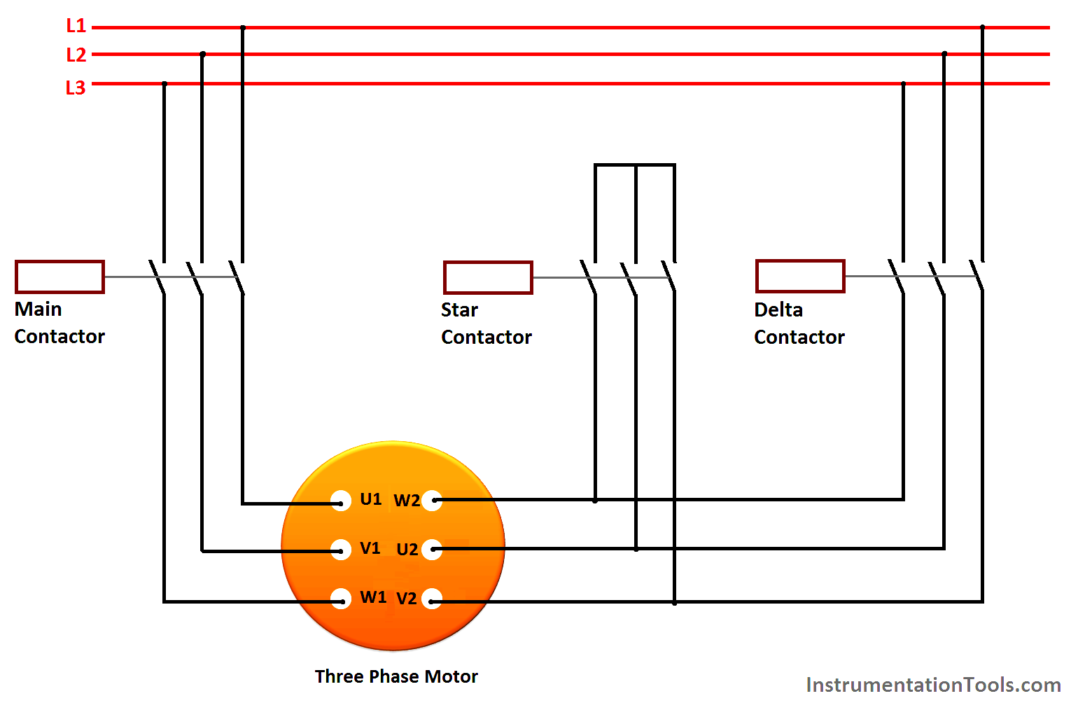
Here the circuit diagram of star delta starter explained in detailhere you will learn the connection of star delta starter with three phase motorthe power circuit diagram and control circuit diagram of an automatic star delta starter are explained belowlets understand the star delta starter diagram. Star delta starter control circuit diagram.

Problem In Star Delta Starter In Air Compressor Electrical
Star delta starter circuit diagram with timer. In my last post i share a star delta starter wiring diagram 3 phase motor connection. There is minor correction is require to change printed in boxes sequence of 3 phase wires from w2 v2 u2 to w2 u2 v2 to get delta connection properly. Star delta starter control circuit diagram is today topic. In this tutorial we will show the star delta y δ 3 phase induction ac motor starting method by automatic star delta starter with timer with schematic power control and wiring diagram as well as how star delta starter works and their applications with advantages and disadvantages. Star delta starter without timer for 3 phase induction motor. The above is a star delta starter wiring diagram 3 phase motor for main wiring.
Now lets see the star delta starter control circuit diagram with timer ncno push button switches. R y b red yellow blue 3 phase linescb general circuit breakermain mai supplyy starδ deltac1 c2 c3 contatcors power diagramol over load relayno normally opennc normally closed k1 contactor contactor coil k1no contactor holding coil. In this post you will learn complete star delta starter wiring with timer normally open push button switch and normally close push button switch. Power control wiring diagram of star delta starter. In the diagram of power circuit of star delta starter u2 and v2 of 3 phase motor should be connect to 4 and 6 respectively instead of u2 and v2 are connected to 6 and 4 of delta contector km2.


