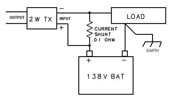
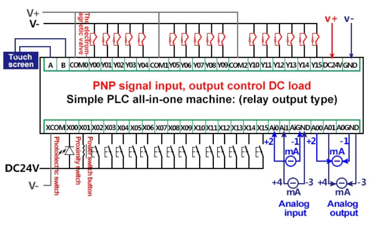
Plc wiring 34 5 vdc ttl 200 240 vac 48 vdc 24 vac plc input cards rarely supply power this means that an external power supply is needed to supply power for the inputs and sensors. Selectable output with analog output of 0 10 vdc.
Rslogix 5000 Analog Input Programming Wiring Scaling
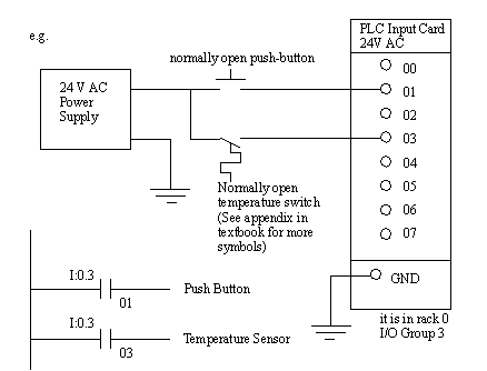
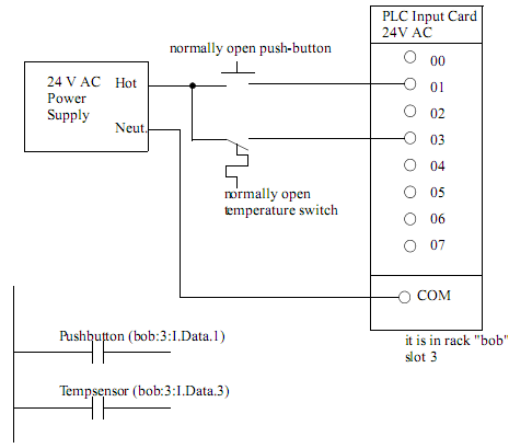
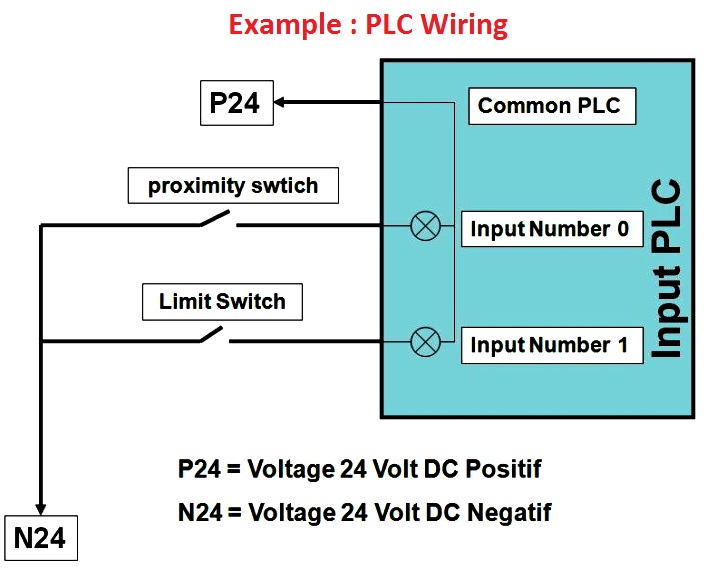
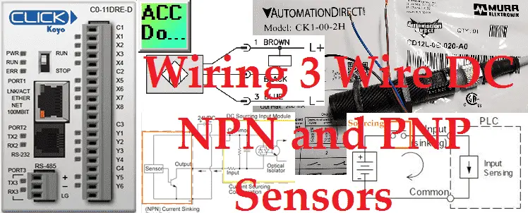
Plc input wiring diagram. The uk1f e7 0a is an 18mm diameter sensor that has a pnp nonc. The following are ten recommended procedures for io wiring. Each rung must start with an input or inputs and must end with at least one output. Commons take advantage of this frequent situation grouping one side of connections together. Note that these diagrams are without a barrier or isolator fuses and surge protector for keeping it very simple and understandable. Check module type and model number by inspection and on the io wiring diagram.
Digital input card in plc basic concept. This will include a discrete and analog input signal. How to follow an electrical panel wiring diagram duration. Calculate the power requirements of all modules in each chassis. Remove and lock out input power from the controller and io before any plc installation and wiring begins. Wiring diagrams wiring diagrams table of contents.
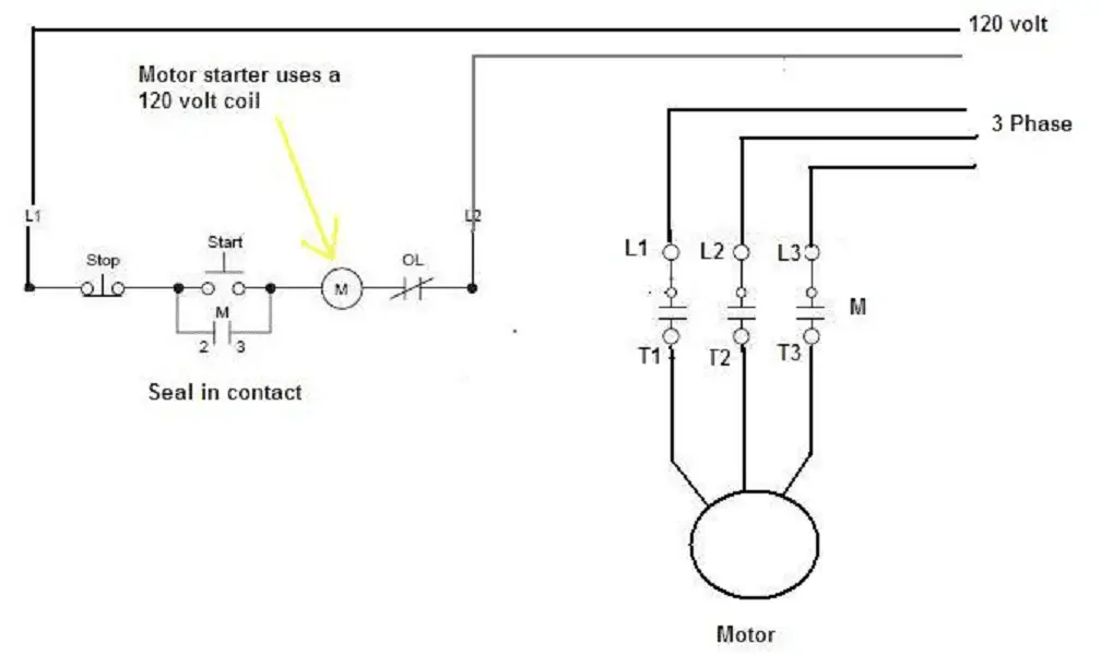
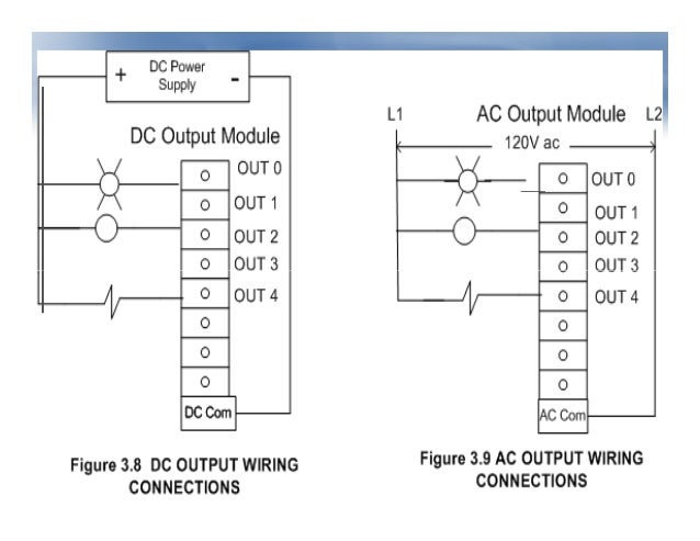
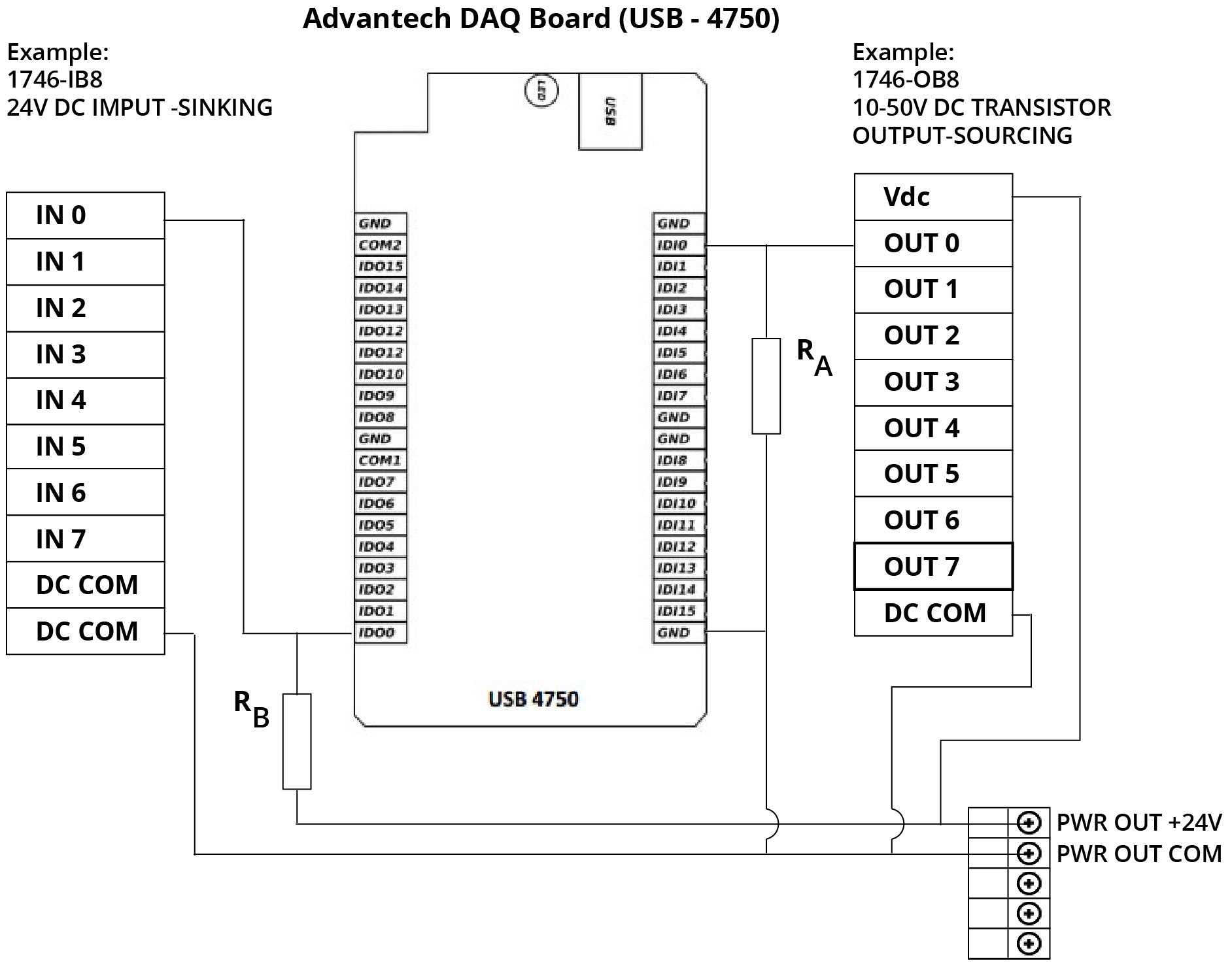
Wiring the input modules field wiring arm configuring your module configuration plugs installing the input module before installing your input module in the io chassis. The picture to the right shows an example of what the wiring of a plc with 4 inputs would look like. Generic wiring diagram allen bradley micrologix 10000 l32bwa allen bradley slc500 schneider m340 bmxddi1602 input module schneider m340 bmxddo1602 output module schneider m340 bmxdra1605 output module schneider tsx 37 micro tsxdmz28dr outputs. Power requirements page 22. The term output is used for a device connected to the output of a plc eg a motor. Plc wiring diagrams guide include the discrete signals wiring plc digital input modules wiring plc output modules wiring and basics of plc terminations.
Determine where to place the module in the io. In this article we are sharing the basic concepts of plc and dcs control systems wiring diagrams for digital input di digital output do analog input ai and analog output ao signals. The sensing distance is 200mm to 2200mm and has a one hertz switching capacity. The term input is used for a control action such as closing the contacts of a switch used as an input to the plc. Analog input card working. In the picture without common the green points all lead to the same voltage source.
We will be wiring an ultrasonic sensor into the input of our click plc. Verify that all modules are in the correct slots.
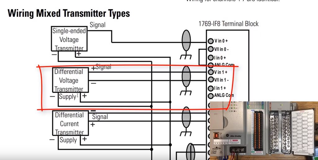
Gallery of Plc Input Wiring Diagram