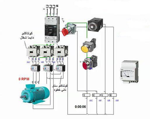
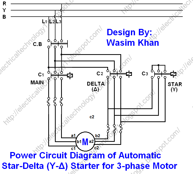
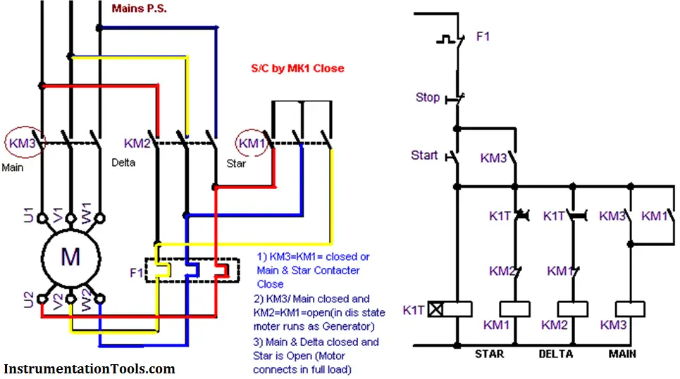
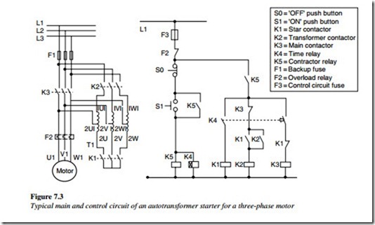
Dosto aaj ki is video me aap dekheenge star delta starter control circuit diagram or kaise kaam karta hai stardeltastartercircuit subscribe yk electrical for electrical videos. In this tutorial we will show the star delta y δ 3 phase induction ac motor starting method by automatic star delta starter with timer with schematic power control and wiring diagram as well as how star delta starter works and their applications with advantages and disadvantages.
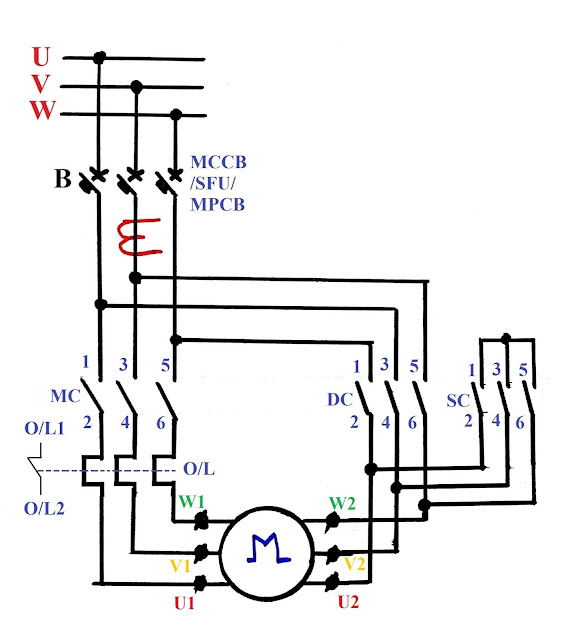
Automatic Star Delta Motor Starter Electrical Technology
Star delta starter control wiring. Overload relay in line. Star delta starter power connection with wiring diagram by evergreenelectrical in this you will learn about star delta power connection with diagram. This is a big advantage of a star delta starter as it typically has around 13 of the inrush current compared to a dol starter. In the above star delta starter control circuit wiring diagram with timer and normally close push buttonnormally open push button switch. A 8 pin timer are used. Here the circuit diagram of star delta starter explained in detailhere you will learn the connection of star delta starter with three phase motorthe power circuit diagram and control circuit diagram of an automatic star delta starter are explained belowlets understand the star delta starter diagram.
In this post you will learn complete star delta starter wiring with timer normally open push button switch and normally close push button switch. Star delta starter control circuit diagram is today topic. A star delta starter is a type of reduced voltage starterwe use it to reduce the starting current of the motor without using any external device or apparatus. Star delta starter without timer for 3 phase induction motor. Star delta starter connection control circuit. In control wiring diagram all magnetic contactors coils are rated 220 vac.
Power control wiring diagram of star delta starter. The on delay timer diagram is also shown in the diagram. Size of over load relay. They are consisting of push buttons two number the green color is for start no p1 and red color for stop nc p2 here no and nc terminology indicate normally open and normally closed. The control circuit is a logic circuit to help us to interchange the motor operation from star to delta. For a star delta starter there is a possibility to place the overload protection in two positions in the line or in the windings.
In the line is the same as just putting the overload before the motor as with a dol starter. R y b red yellow blue 3 phase linescb general circuit breakermain mai supplyy starδ deltac1 c2 c3 contatcors power diagramol over load relayno normally opennc normally closed k1 contactor contactor coil k1no contactor holding coil. Size of each part of star delta starter 1. In my last post i share a star delta starter wiring diagram 3 phase motor connection. We will also show you star delta starter.


