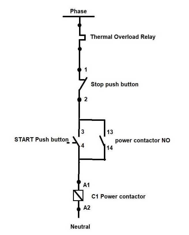
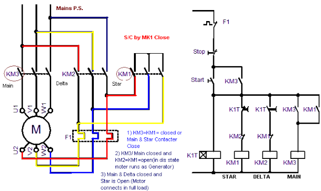
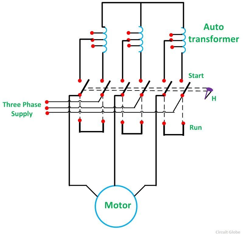
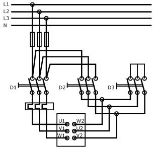
Star delta starters consist of a power circuit and control circuit. Star delta connection diagram and working principle.

Star Delta Wiring Diagram In Pdf
Star delta starter wiring diagram pdf. A dual starter connects the motor terminals directly to the power supplyhence the motor is subjected to the full voltage of the power supplyconsequently high starting current flows through the motor. This type of starting is suitable for small motors below 5 hp 375 kw. Star delta connection circuit diagram. There is minor correction is require to change printed in boxes sequence of 3 phase wires from w2 v2 u2 to w2 u2 v2 to get delta connection properly. First the on button is pushed and the contactor s gets energized. In this tutorial we will show the star delta y δ 3 phase induction ac motor starting method by automatic star delta starter with timer with schematic power control and wiring diagram as well as how star delta starter works and their applications with advantages and disadvantages.
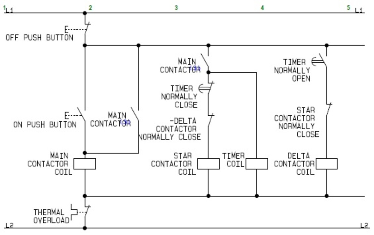
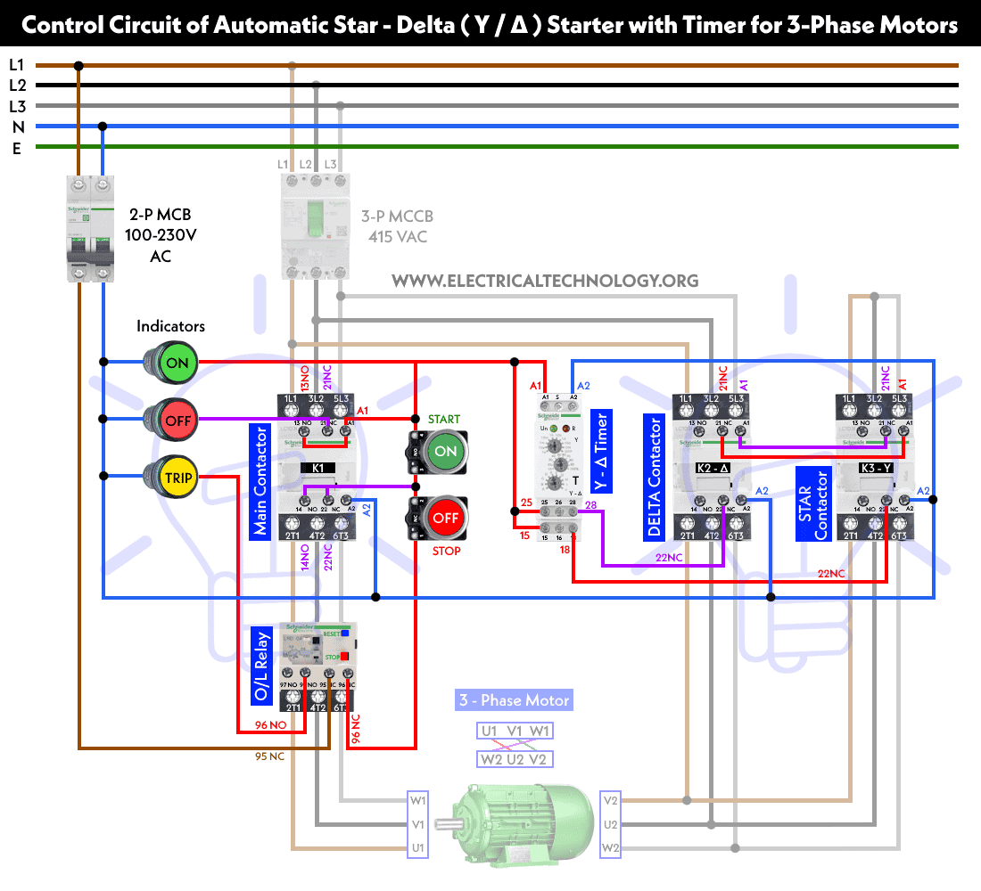
But there is a significant difference in the control circuit which is shown in the following image. In the diagram of power circuit of star delta starter u2 and v2 of 3 phase motor should be connect to 4 and 6 respectively instead of u2 and v2 are connected to 6 and 4 of delta contector km2. The control circuit uses to control the starter circuit such as on off and tripping operations. The power circuit uses to create contact between the motor and three phase power supply. Eaton wiring manual 0611 8 1 88 all about motors page motor protection 8 3 notes on engineering 8 15 circuit documents 8 19 power supply 8 21 control circuit supply 8 24 contactor markings 8 25 direct on line start of three phase motors 8 26 control circuit devices for direct on line start 8 34 star delta switching of three phase motors 8 35. Refer to the below star delta circuit.
The wiring diagram of an automatic star delta starter is same as that of the semi automatic star delta starter.
