A stepper motor also known as step motor or stepping motor is a brushless dc electric motor that divides a full rotation into a number of equal steps. Eastern geek 134945 views.
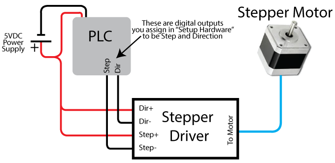
Plc Stepper Motor Control Velocio Net
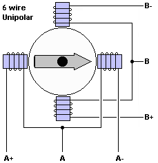
Stepper motor connection diagram. How to properly connect a stepper motor to unipolar or bipolar drivers duration. The following information is intended as a general guideline for wiring of the stepper motors. 4 wire stepper motor connection diagram wiring diagram is a simplified suitable pictorial representation of an electrical circuitit shows the components of the circuit as simplified shapes and the facility and signal connections amid the devices. A stepper motor driver usually consists of a controller a driver and the connections to the motor. This is a really easy method to identify a matching set of coils for a stepper motor when the vendor or manufacturer doesnt have it or wont provide it. The motors position can then be commanded to move and hold at one of these steps without any position sensor for feedback an open loop controller as long as the motor is carefully sized to the application in respect to torque and speed.
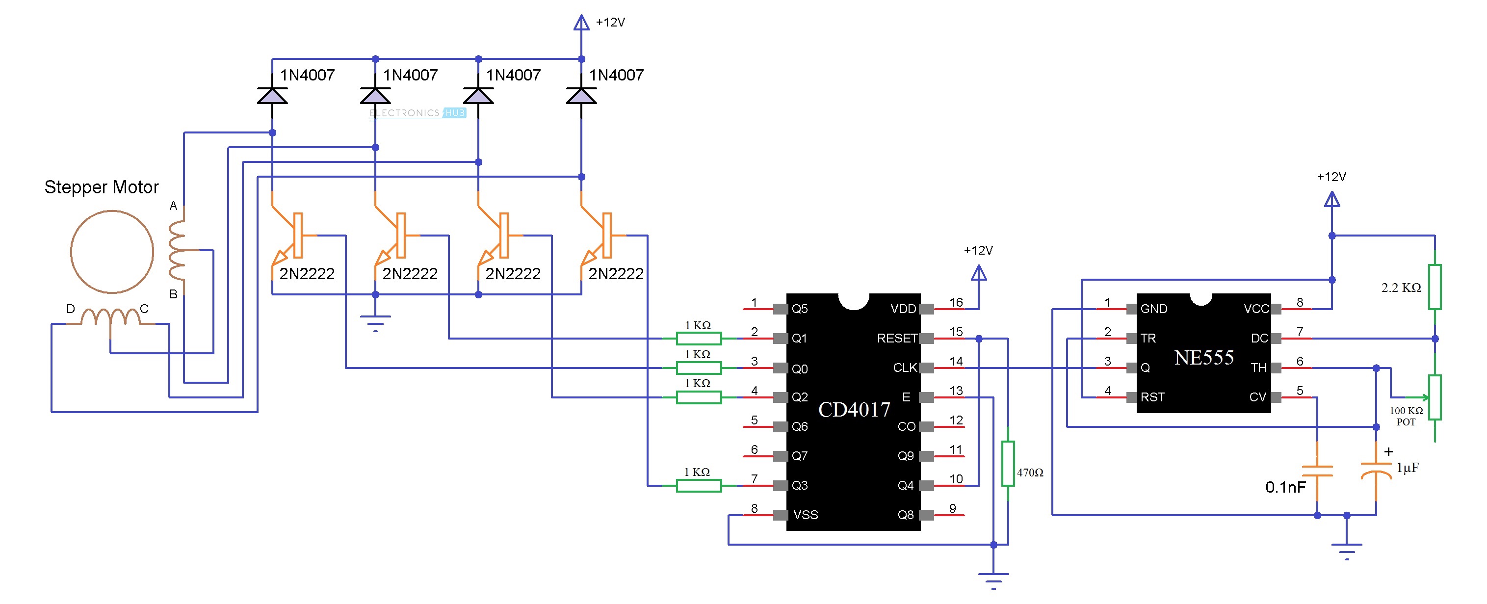
It is often called a stepper motor driver. Assortment of stepper motor wiring diagram. It shows the components of the circuit as simplified forms as well as the power and also signal links in between the tools. Be aware that when you route power and signal wiring on a machine or system radiated noise from the nearby relays transformers and other electronic devices can be introduced into the stepper motor and encoder signals inputoutput communications and other sensitive low. Stepper motor basics 5 wires unipolar bipolar motor duration. Since coils a and b on the diagram above are not connected the resistance between leads a1 and b1 or between a1 and b2 will be infinite.
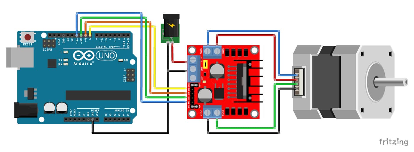
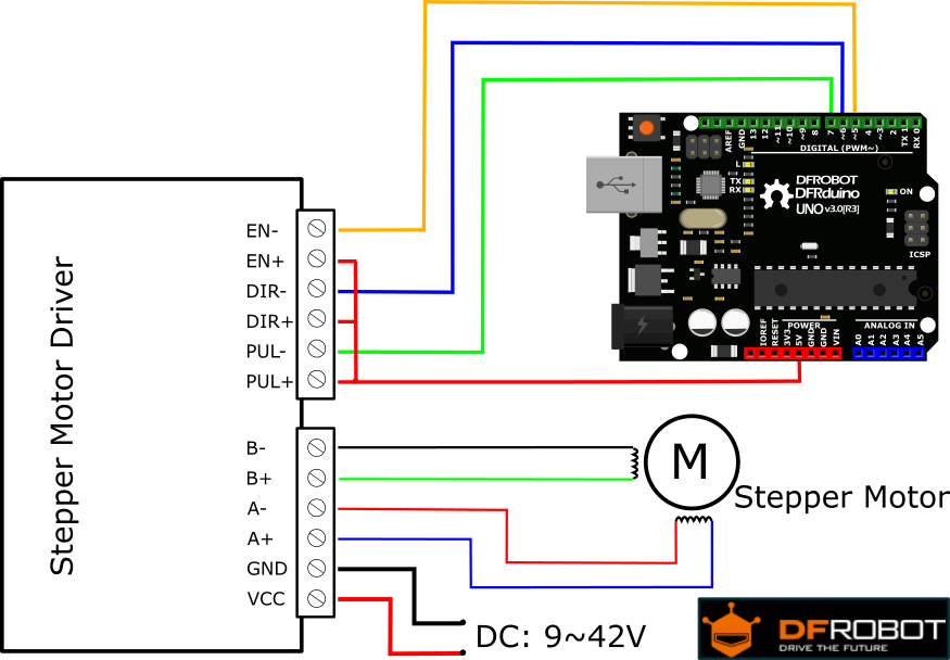
Assortment of wantai stepper motor wiring diagram. It reveals the components of the circuit as streamlined forms and also the power and also signal connections between the tools. If your stepper motor has 4 wires it is a bipolar stepper motor. Connect stepper motor to arduino. A stepper motor driver or stepper motor drive is a circuit which is used to drive or run a stepper motor. A wiring diagram is a simplified standard pictorial representation of an electrical circuit.
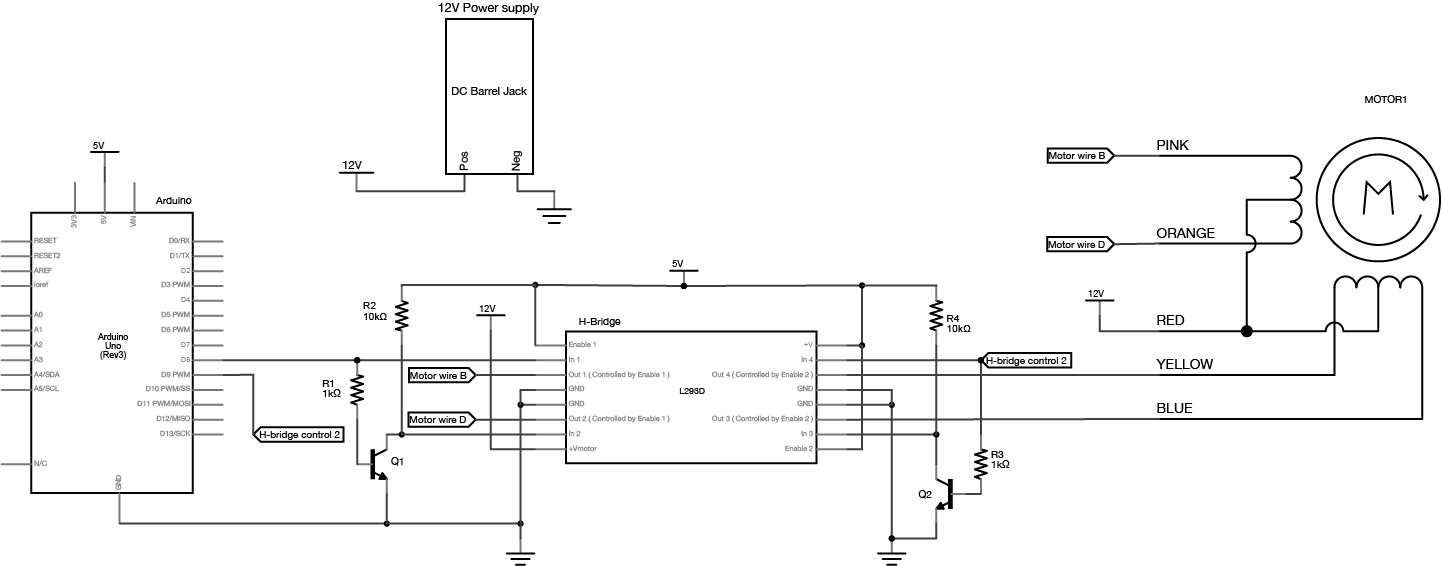
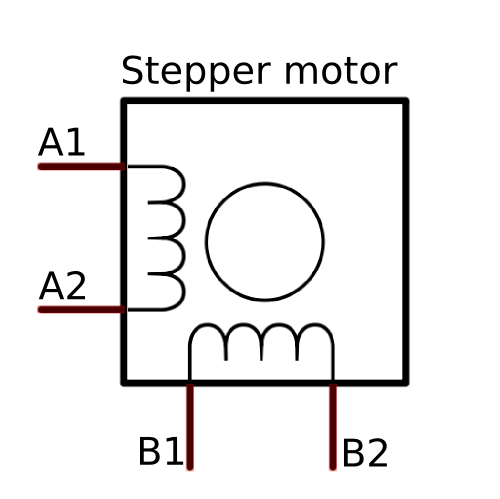
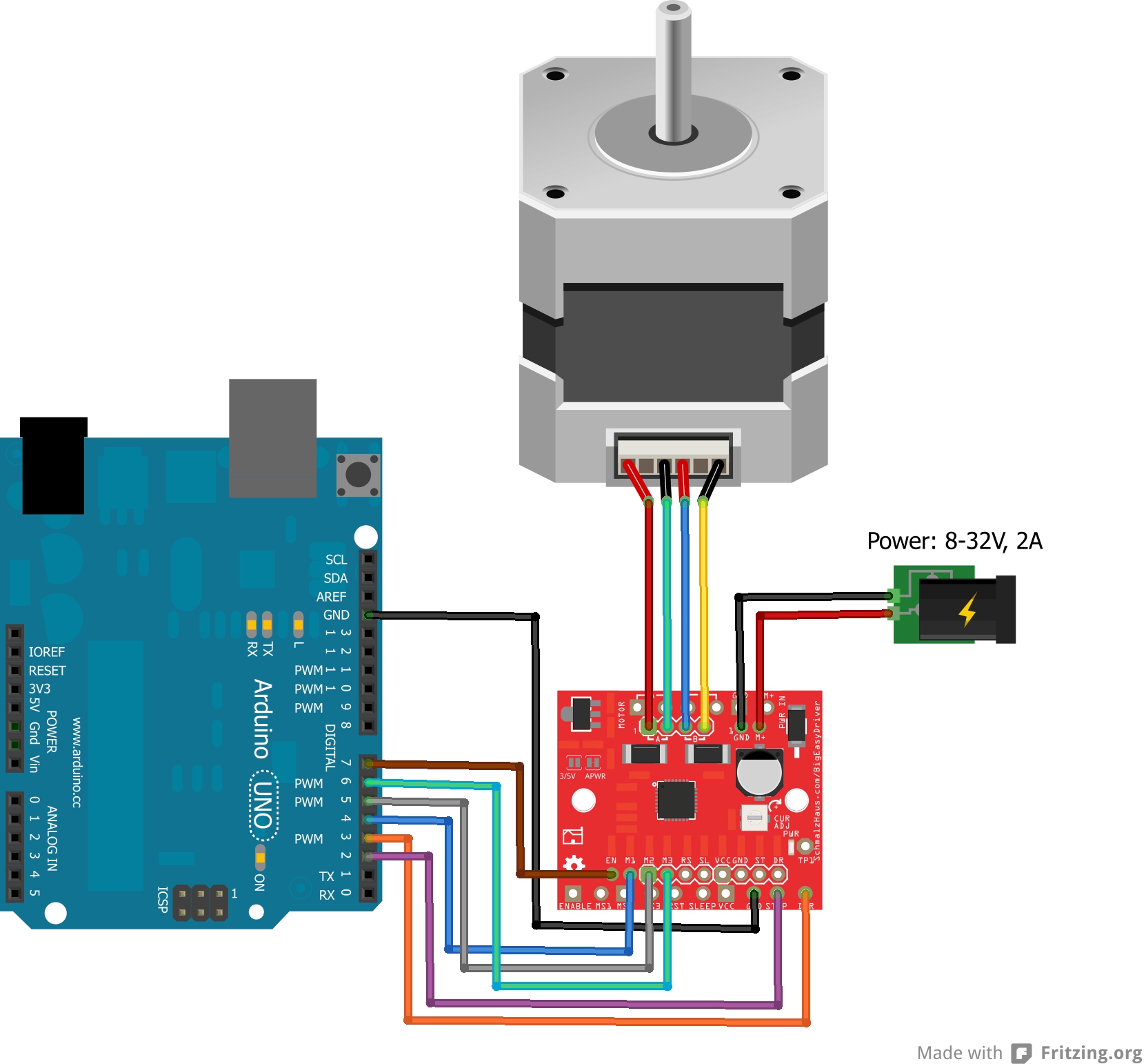
For questions and quotes please contact. In this tutorial i will help you to connect an unipolar stepper motor to your arduinoto do this youll need 1x arduino board on ebay aprox 101x driver for stepper they are cheap on ebay just type in ebay uln2003 stepper m. A wiring diagram is a simplified standard pictorial representation of an electrical circuit. Bipolar stepper motors have two windings which are not connected to each other wired internally like this.
