In short this the complete guide of forward reverse starter. Typical wiring diagram line diagrams show circuits of the operation of the controller.

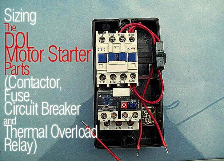
Sizing The Dol Motor Starter Parts Contactor Fuse Circuit
Three phase motor starter wiring diagram. All connection i shown with complete guide. It uses two contactors two auxiliary contact blocks an overload relay a mechanical interlock two normally open start pushbuttons a normally closed stop pushbutton and a power supply with a fuse. That being said there is a wide range of different motors and what you have on hand can be completely different. In the united states for low voltage motors below 600v you can expect either 230v or 460v. Line diagrams also called schematic or elementary dia grams show the circuits which form the basic operation of the controller. The first step is to figure out the voltage of your phases.
Is a typical wiring diagram for a three phase mag netic starter. This diagram is for 3 phase reversing motor control with 24 vdc control voltage. In the above three phase dol starter wiring diagram. Three phase motor connection stardelta without timer power control diagrams. The 3 phase incoming supply shown l1 l2 l3. Time lapse of schematic diagram drawn into a wire diagram and the wiring of the magnetic motor starter.
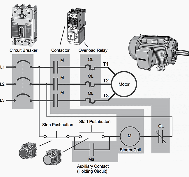
1 phase 2 phase 4 wire 3 phase line markings l1 l2 l1 l3. I shown the 3 pole mccb circuit breaker 2 magnetic contactor normally open normally close push button switch thermal overload relay 3 phase 4 wire system supply 3 phase motor with connection trip indicator light etc. The three phase supply is connected the mccb circuit breaker. Star delta y δ 3 phase motor starting method by automatic star delta starter with timer. A wiring diagram is a streamlined conventional photographic representation of an electrical circuit. In the 3 phase motor forward reverse starter wiring diagram.
Ac manual starters and manual motor starting switches 12 class 2510 12 class 2511 and 2512 13 2 speed ac manual starters and. Assortment of 3 phase motor starter wiring diagram pdf. Wiring diagram book a1 15 b1 b2 16 18 b3 a2 b1 b3 15 supply voltage 16 18 l m h 2 levels b2 l1 f u 1 460 v f u 2. Dol starter wiring diagram for three phase motor to wire a 3 phase motor the first thing to wire is a circuit breaker which is disconnect and connecting point then we will get the supply from circuit breaker and connect supply to contactor or starter and then to overload relay. Three phase motor connection schematic power and control wiring installation diagrams. A three phase motor must be wired based on the diagram on the faceplate.
Phase 2 l1 l2 l3. It shows the parts of the circuit as simplified shapes and also the power and also signal links in between the tools. From where we can switch off the incoming supply to the direct online starter. Phase 1 l2 l4. They do not indicate the physical relation.


.jpg)


