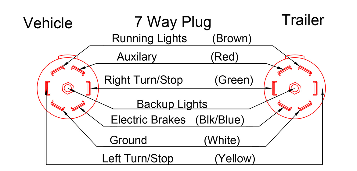
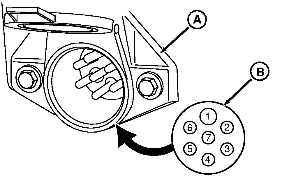
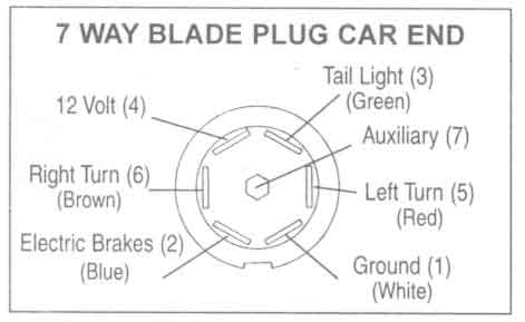
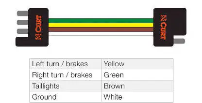
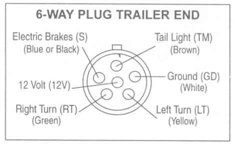
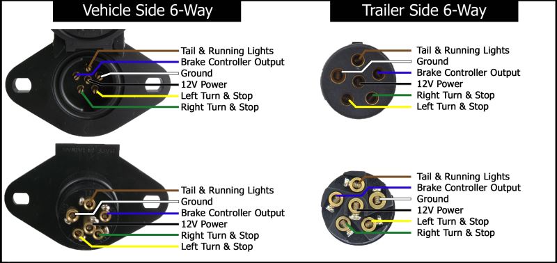
I have a 2020 3500 chev pk up with factory brake control wiring. These 2 wire diagrams fit the needs for most trailers.

1989 Gm Charging Diagram Trailer Plug Wiring Diagram Gm
Trailer plug wiring schematic. However i have 3 trailers 2 work fine 1 dont. 7 way plug wiring diagram standard wiring post purpose wire color tm park light green battery feed black rt right turnbrake light brown lt left turnbrake light red s trailer electric brakes blue gd ground white a accessory yellow this is the most common standard wiring scheme for rv plugs and the one used by major auto manufacturers today. Typical trailer wiring diagram and schematic. Above we have describes the main types of trailer wiring diagrams. Extrapolate the same expansion for additional axles. To connect the electric system of your trailer to the vehicle you will be using special connector.
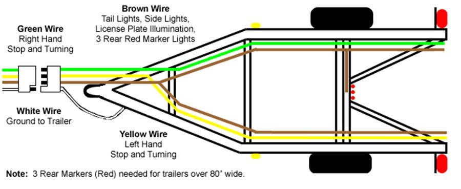
Below is the generic schematic of how the wiring goes. 4 pin trailer wiring diagram. The image above shows a single axle trailer and the next image shows wiring for tandem axles. I have no power to any light pins on 7 wire plug wtester. Trailer wiring diagram wiring diagrams for trailers international 1 989 755 0561 toll free 1 800 358 4751 covid 19. Various connectors are available from four to seven pins that allow for the transfer of power for the lighting as well as auxiliary functions such as an electric trailer brake controller backup lights or a 12v power supply for a winch or interior trailer lights.
Use this handy trailer wiring diagram for a quick reference for various electrical connections for trailers. Trailer wiring diagrams trailer wiring connectors. Only the blue brake and white ground wires are different.


