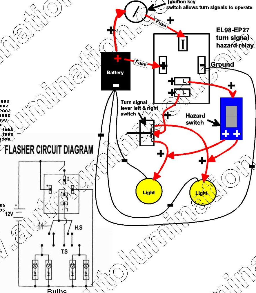
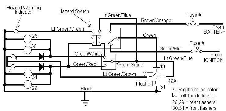
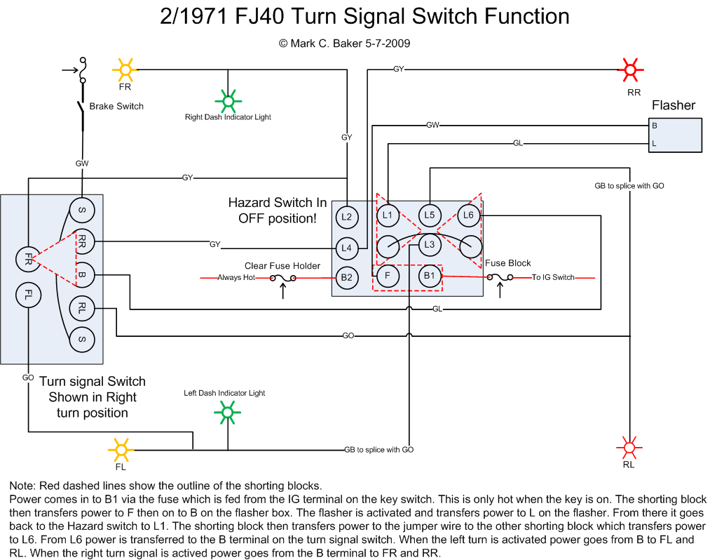
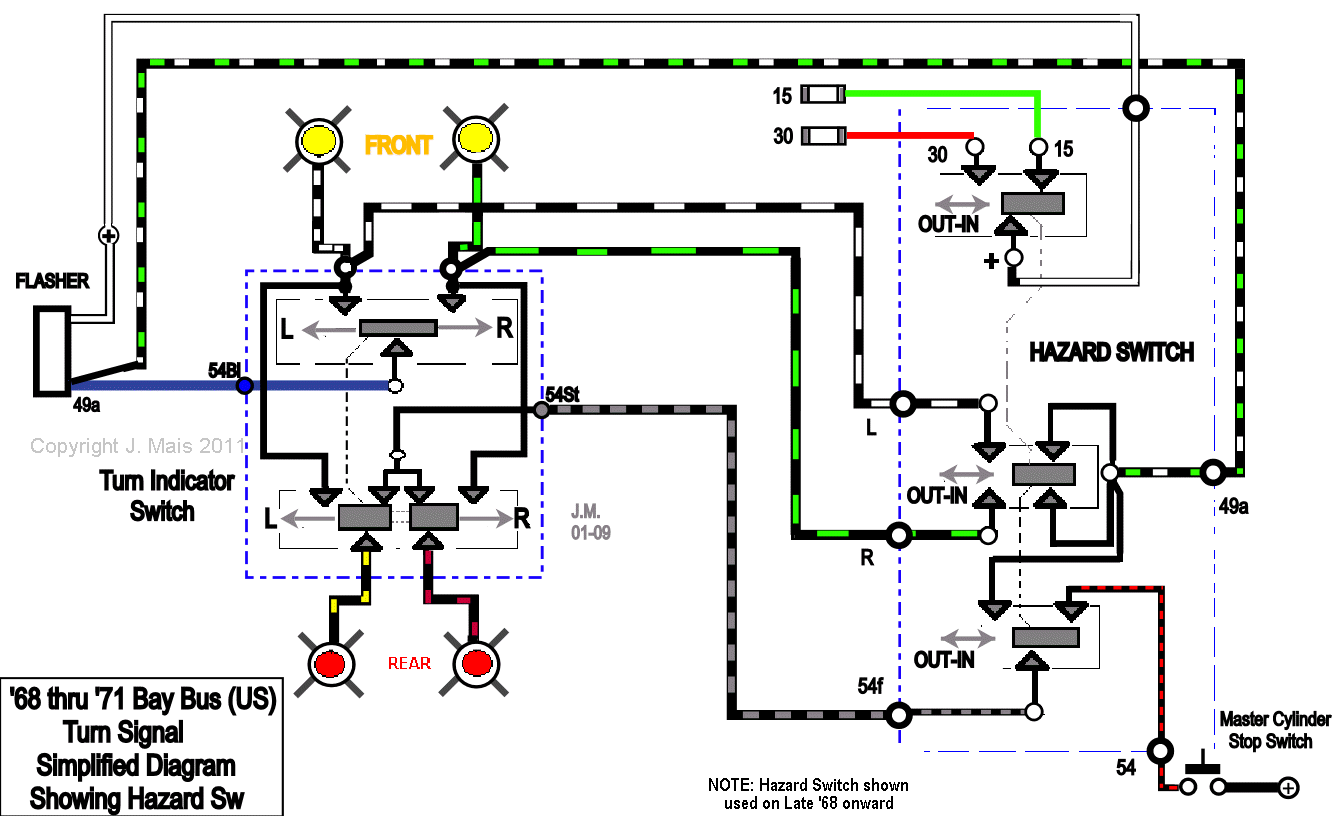
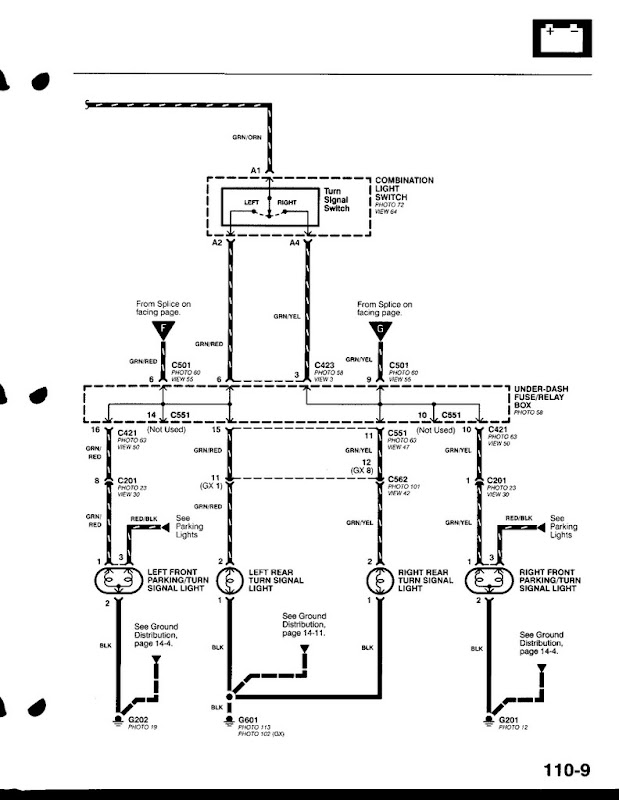
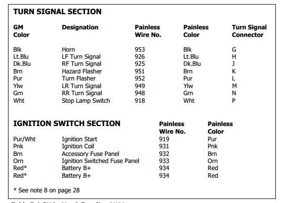
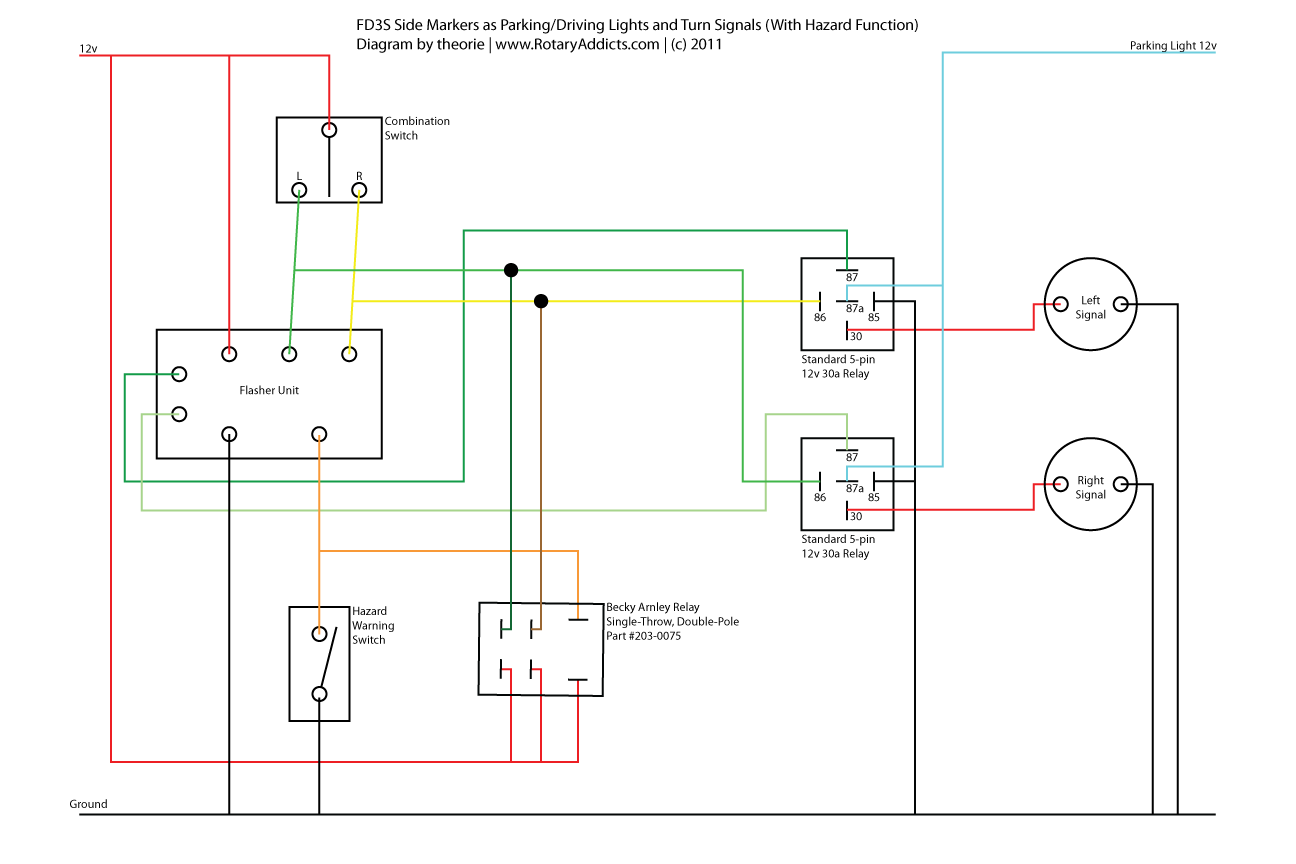
Early bus hazard wiring 62 thru 65 models used a switch and a relay to provide 4 way flashing hazard lights. Right rear turn signal to the rear of the vehicle and attach.

Mazda Mpv Tail Light Wiring Diagram Kawasaki 10
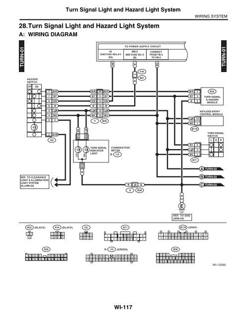
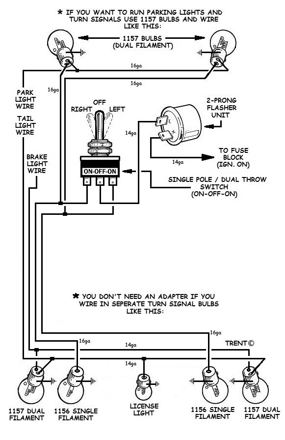
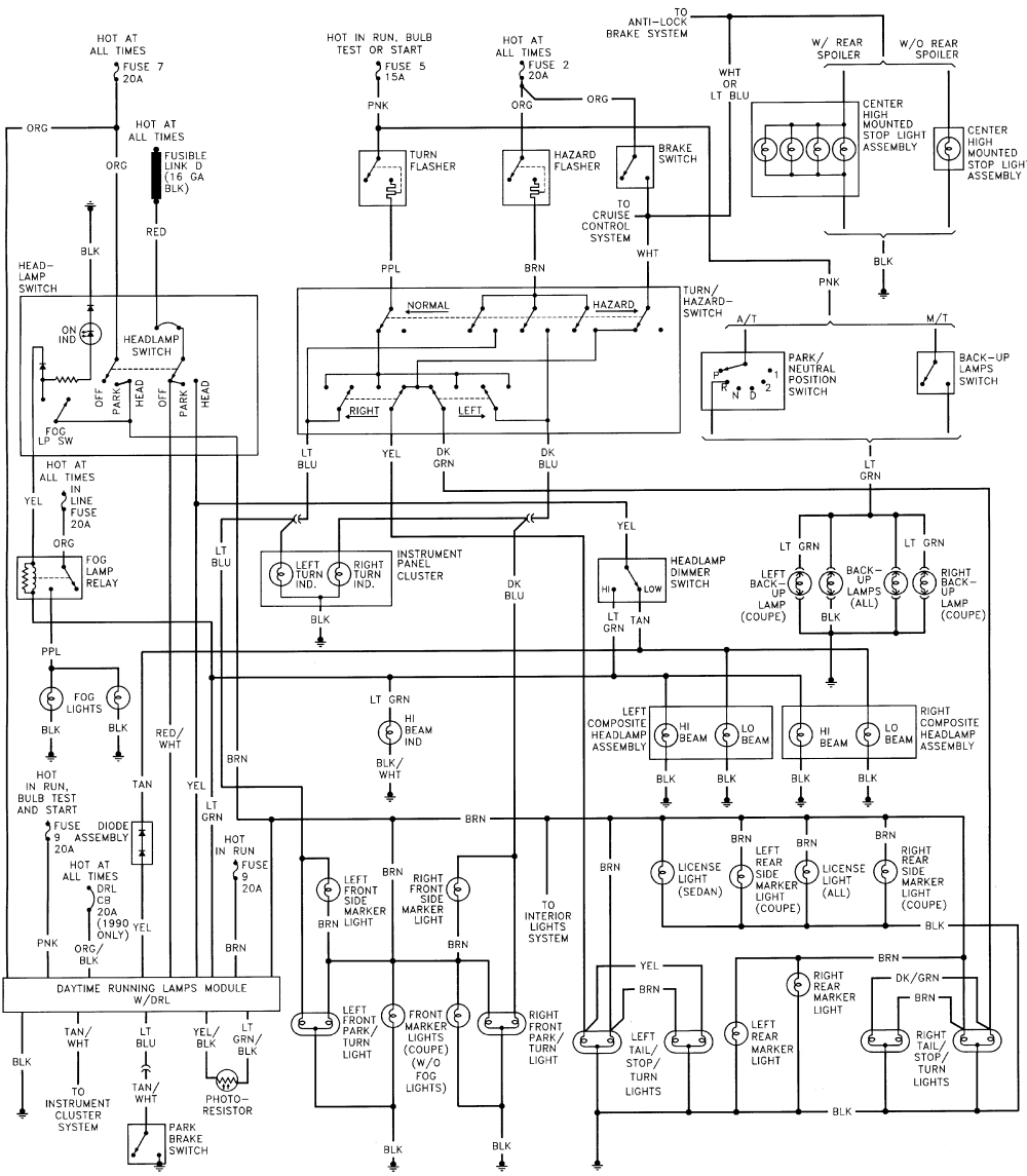
Turn signal and hazard light wiring diagram. If not the structure wont work as it ought to be. They will combine the brake wiring and the turn signal wiring so they will work. Each part should be placed and linked to other parts in specific way. Motofix ph send me stuff. The yellow and green wires will serve as the brake light and turn power wires to each light which will replace any existing brake light wires. You can get them at places like napa or here.
Variety of universal turn signal wiring diagram. Some have the tail light wire running through them 4 wire into 3 wire and some dont 3 wire into 2 wire. The relay in turn powered both left and right front indicators from a separate fuse source. Comment subcribe do it at your own risk follow me on facebook. A quick and cheap way that works just as good is a tail light wiring converter for trailers. It shows the parts of the circuit as simplified forms and also the power and also signal links in between the devices.
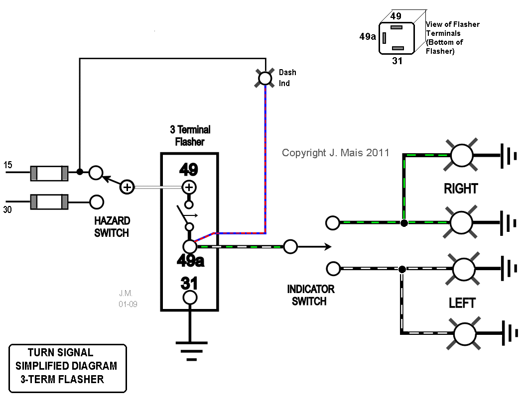
10 reconnect the vehicles negative battery cable. They look like this. Turn signal flasher wiring diagram led turn signal flasher wiring diagram motorcycle turn signal flasher wiring diagram turn signal flasher circuit diagram every electric arrangement consists of various unique parts. Turn signal circuits are often an area of trouble for technicians. The switch connected both rear lights to the flasher and simultaneously connected a relay to the flasher. 11 with the ignition switch on flip the turn toggle switch to the left and the.
A wiring diagram is a streamlined standard pictorial depiction of an electric circuit. In all cases the turn signal switch is also in charge of the hazard lights and to make matters worse the hazard and the turn.
