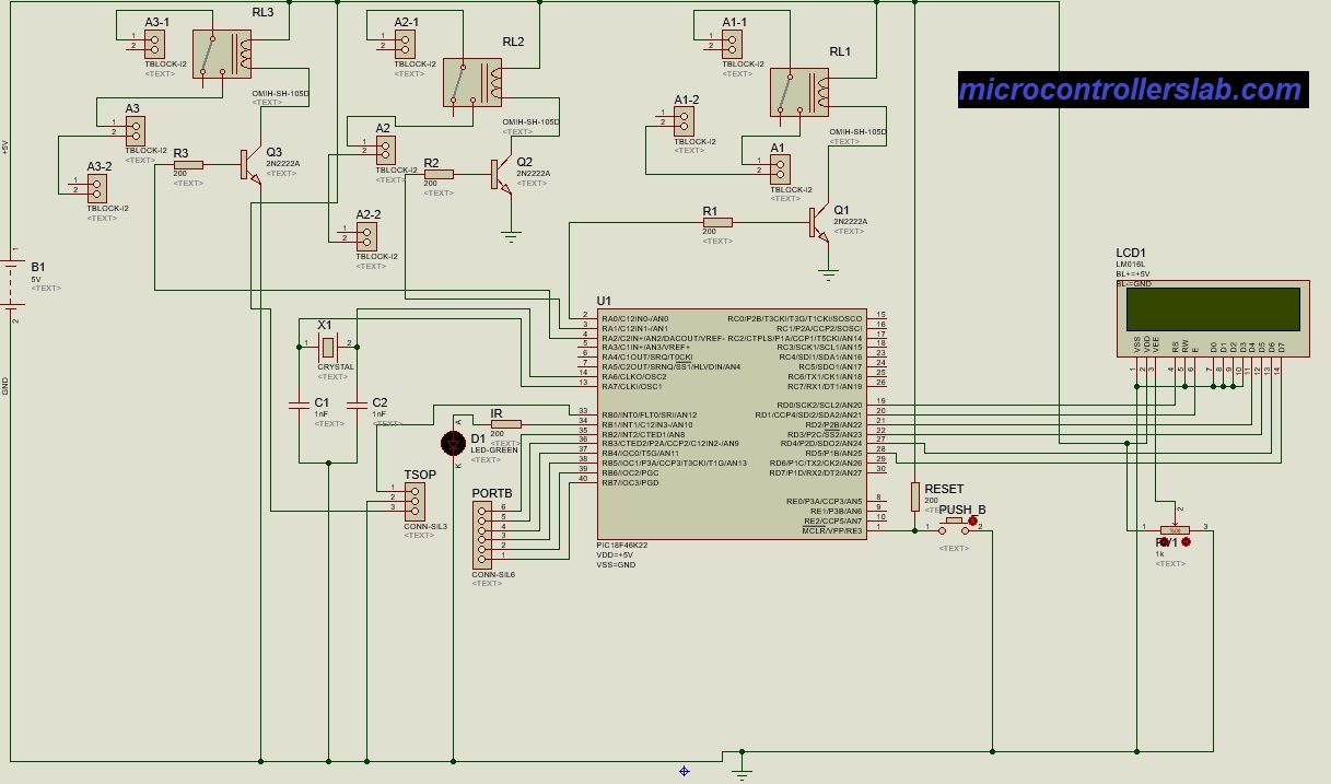
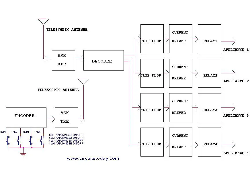
Tv remote control jammer circuit principle. Block diagram of infrared remote control switch.

Ir Infrared Remote Control Switch Circuit And Applications
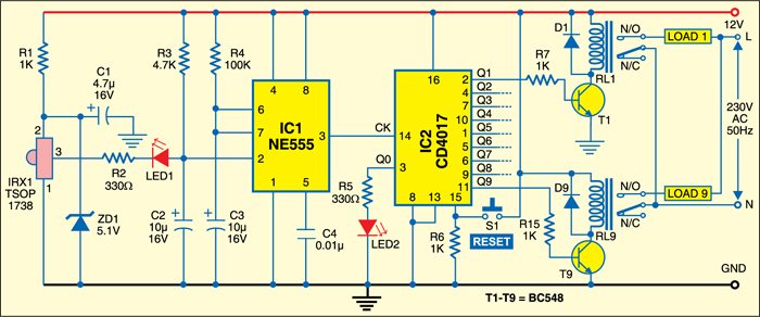
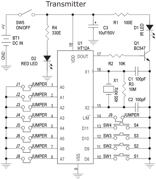
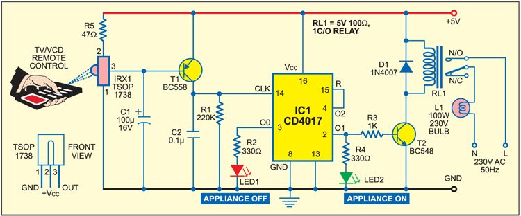
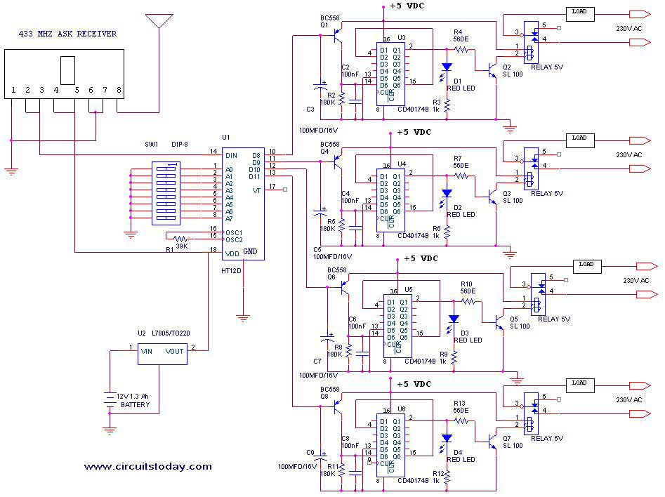
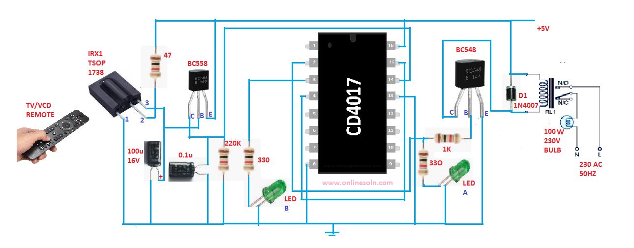
Tv remote control circuit diagram. In this remote controlled switch circuit we are using tv remote to onoff the ac light by pressing any button of remote and using the tsop1738 at receiver end. In this circuit we are using one switch for operating the transmitter with this we can switch on or off the tv motor radio or any other home appliances. Electronic parts are assembled on printed circuit boards because they are easy to mass produce. Receiver circuit is connected to ac appliance via relay so that we can control the light remotely. Remote control circuit through radio frequency without microcontroller description this is a simple type remote control by using rf communication without microcontroller. The communication between tv and remote control is ir infra red communication.
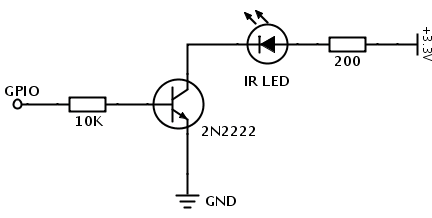
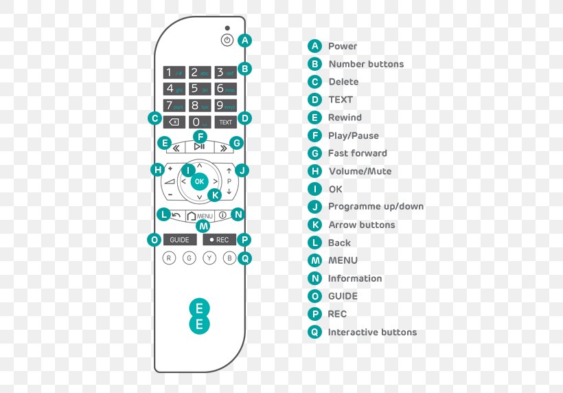
Here is the circuit diagram of an fm remote encoderdecoder using the ics rf600e and rf600d. Hence the result will be non accepted signal from the receiver and therefore no action will be taken. We uses normal switch in our daily life and after a long time used to these swithing system we can no more interested in that. The proposed infrared or ir remote control circuit can be used to operate an appliance onoff through any standard tv remote control handset. Inside a tv remote control. So basically this circuit is a ir jammer circuitas shown in below image the remote consists of an ir infrared led which blinks every time a button is pressed.
In this write up we discuss a couple of these simple infrared remote control circuits designed for controlling any given electrical appliance through an ordinary or tv remote control unit. This is a good solution for a unique and so interesting idea to wireless switching system to control the home appliance. Here is the circuit diagram of simple but highly effective tv. This is the very simple circuit diagram of ir remote control switch. A simple remote tester circuit using just 2 transistors can be seen in the above figure. Basically the tv remote emits a sequence of pulses when you press a button.
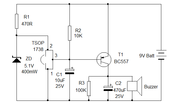
The idea behind the tv remote control jammer is sending a constant ir pulse with the carrier frequency of the transmitter. When the remote control handsets button is pressed and pointed towards the photodiode of the circuit the photodiode begins conducting and allows a few mv to pass through it. The working of the design is self explanatory. When you unscrew the circuit board and take it out you can see that the circuit board is a thin piece of fiber glass that has thin copper wires etched onto its surface. We have used ic 4017 to convert it into a push on push off switch. The main function of this remote control switch is to control any load tv radio stereo fan light etc.
Gallery of Tv Remote Control Circuit Diagram