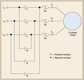
Manual motor starters are simply manual switches designed to control larger current loads typical of motor control. Phase 1 l2 l4.
Ebook Automating Manufacturing Systems With Plcs
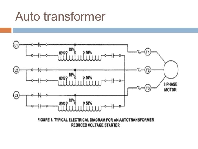
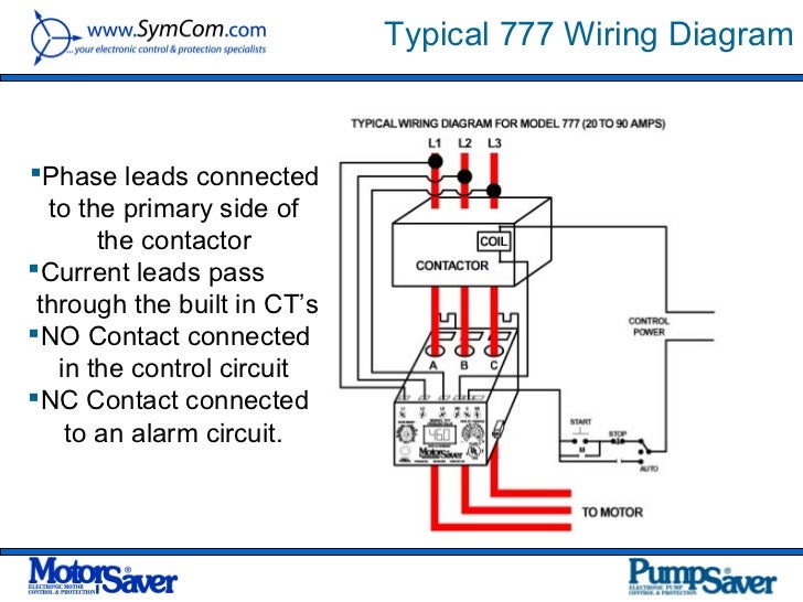
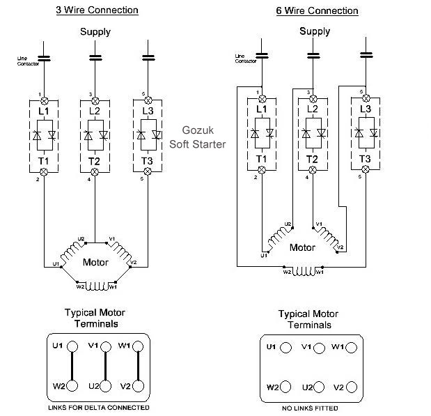
Typical motor starter wiring diagram. Typical controller markings typical elementary diagram iec typical controller markings typical elementary diagram table 4 control and power connections for across the line starters 600 v or less from nema standard ics 2 321a60 1 phase 2 phase 4 wire 3 phase line markings l1 l2 l1 l3. Figure 1 is a typical wiring diagram for a three phase mag netic starter. Figure 1 is a typical wiring diagram for a three phase magnetic motor starter. They can be used as a guide when wiring the controller. They may be small and similar to the light switches in your home or they may be much larger dedicated switches designed for control of high amperage circuits. Variety of starter solenoid wiring diagram chevy.
It shows the parts of the circuit as simplified shapes and also the power and also signal connections between the gadgets. Be used as a guide when wiring the controller. In north america an induction motor will typically operate at 230v or 460v 3 phase 60 hz and has a control voltage of 115 vac or 24 vdc. Motor starter wiring diagrams print. Basic wiring for motor control technical data. A wiring diagram is a simplified traditional photographic representation of an electric circuit.
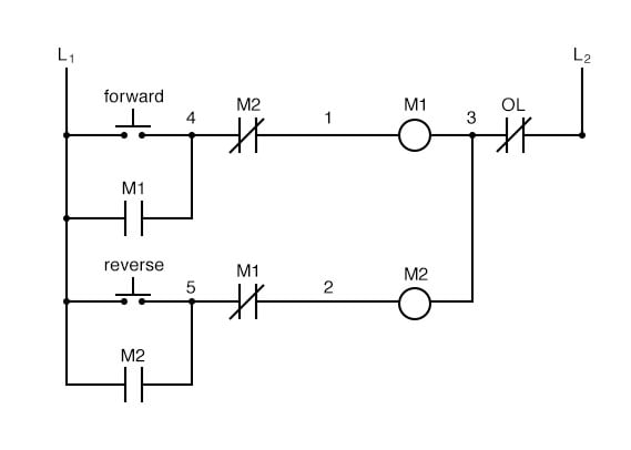
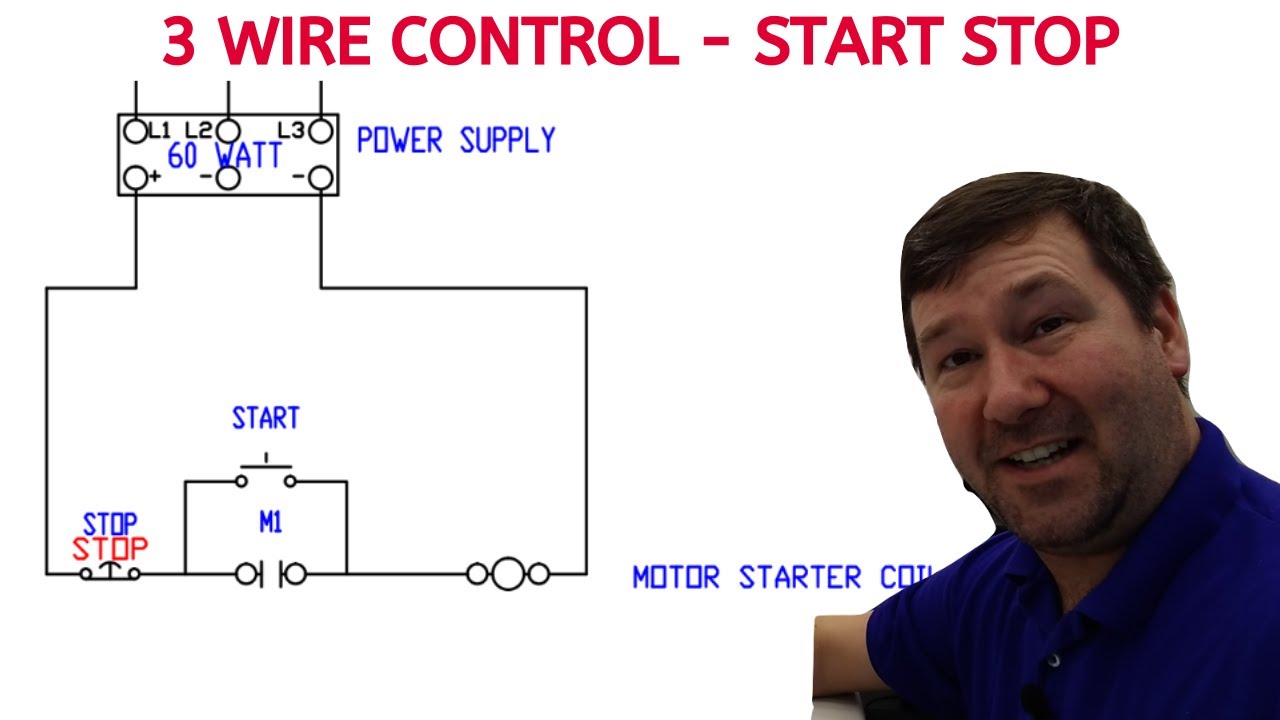
The same manner as a typical up down pushbutton station. The specific circuit needs to be respectively learned referring to different typical control circuits. Motor control circuits. They show the relative location of the components. A motor starter is a combination of devices used to start run and stop an ac induction motor based on commands from an operator or a controller. Note the control circuit is a three wire ladder diagram control circuit which works well for smaller horsepower three phase motors.
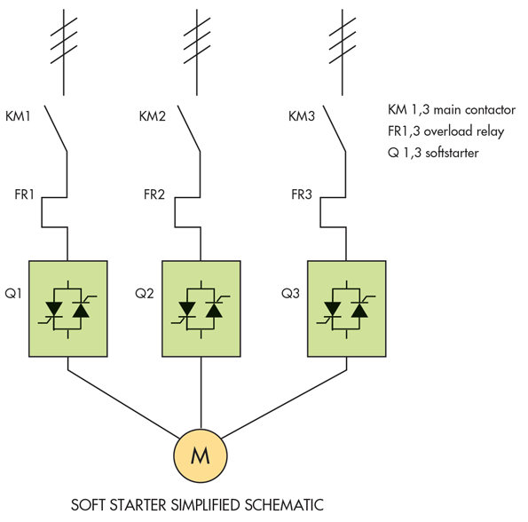
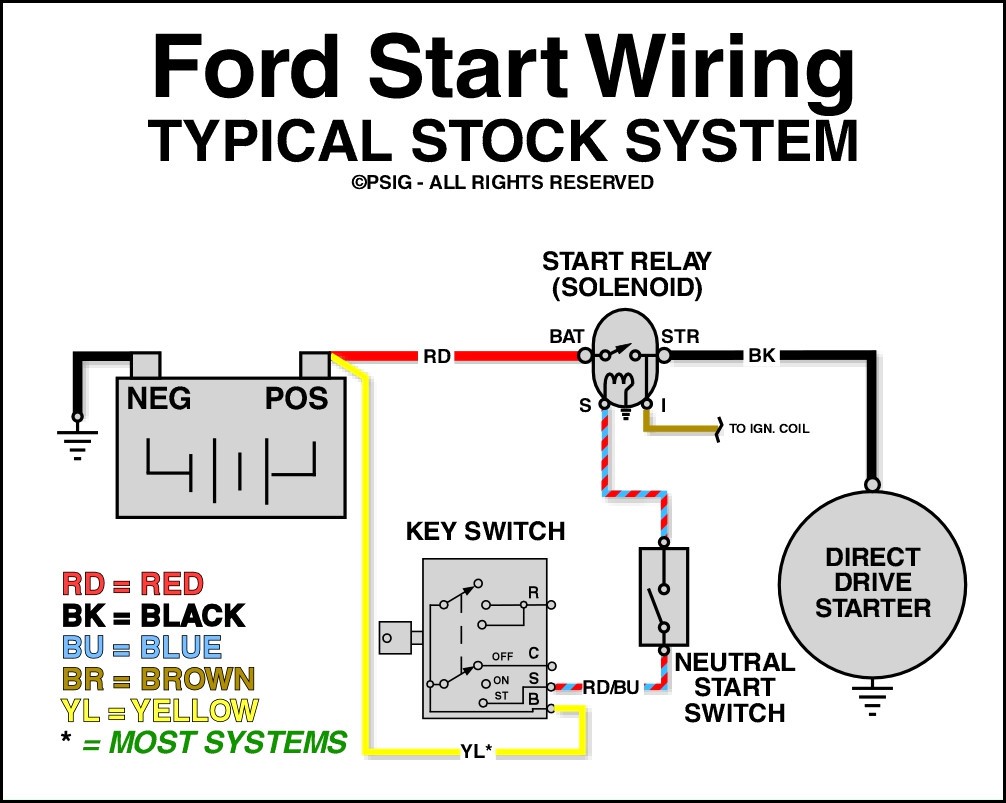
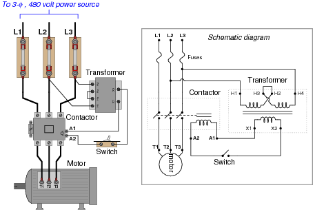
The typical starting system wiring diagrams can divide into non relay control type single starter relay control type and security starter relay control type. This diagram shows both the power circuit and the control circuit. These motor starters consist of an on off snap switch combined with a thermal overload device operating on the eutectic alloy ratchet principle. Phase 2 l1 l2 l3 ground when used. Your motor starter. Lever mounted on the front of the switch.
Typical wiring diagram line diagrams show circuits of the operation of the controller. In the motor starter fairly close to the coil as shown in figure 13b and the normal physical appearance. The diagram for a typical full voltage across the line starting circuit is shown in figure 1. Figure 1 typical wiring diagram. Wiring diagrams do not show the operating mechanism since it is not electrically controlled. Line diagrams also called schematic or elementary dia grams show the circuits which form the basic operation of.
Many motors are controlled by computerized con.
Gallery of Typical Motor Starter Wiring Diagram