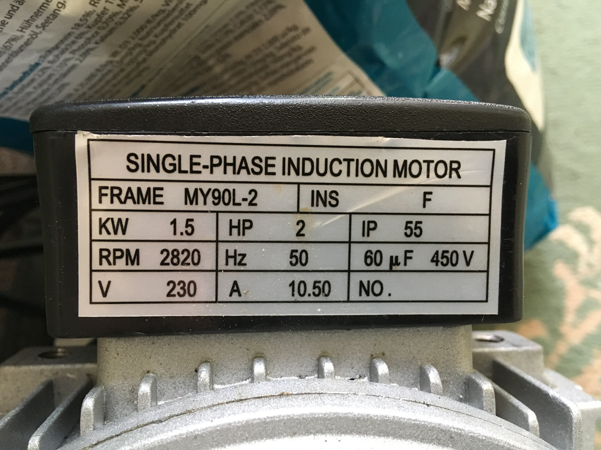
15 kw 1330 rpm 50 hz 94 amps capacitor details. As a guide for the equivalent sized single phase motor eg.

Star Delta Starter Plc Program And Wiring Part 5
U1 v1 w1 motor wiring single phase. Hi ive recently bought a clarke induction motor with these specs. U1 or red u1 or red v1 or yellow v1 or yellow w1 or blue w1 or blue thermal contacts tb white thermal contacts tb white l1 l1 l2 l2 l3 l3 e e codes. And upwards diagram dd5 two speed motors for all other single phase wiring diagrams refer to the manufacturers data on the motor. And upwards diagram dd5 two speed motors for all other single phase wiring diagrams refer to the manufacturers data on the motor. U1 u2 z2 u1 u2 z2 l1 n l1 n cstart cstart u1 u2. U1 or red u1 or red v1 or yellow v1 or yellow w1 or blue w1 or blue thermal contacts tb white thermal contacts tb white l1 l1 l2 l2 l3 l3 e e codes.
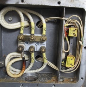
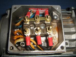
It is a two capacitor startrun motor but the terminals are marked u1u2v1v2w1w2 etc. U1 w1 v1 u2 w2 v2 t1 t2 5 u1w1 v1 u2 w2 v2 t1 t2 f1f2 u2 w2 v2 t1 t2 terminal board motorized pulley 230v thermal potector thermal potector thermal potector l1 r l2 s l3 t u1 w1 v1 u2 w2 v2 t1 t2 high voltage y high voltage y high voltage y low voltage thermal potector l1 r l2 s l3 t l1 r l2 s l3 t l1 r l2 s l3 t. The rotation of the motor is not important. Wellingborough nn8 4hn wwwexicocouk tel 01933 277930 fax 01933 272184 wiring diagram single phase motors 1empc permanent capacitor motors. L1 l2 l3 join high wye u1 v1 w1 u2v2w2 low delta. In the terminal box there are 6 terminals labled v1 v2 u1 u2 w1 w2.
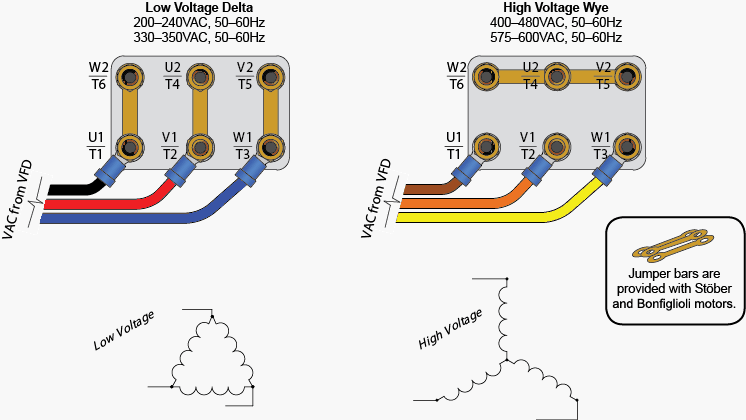
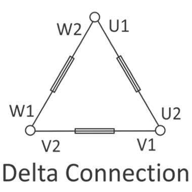
L1 l2 l3 join mode start wye u1 v1 w1 u2v2w2 run delta u1w2 v1u2 w1v2 dual voltage volt. Wiring information for standard single phase electric motors. W2 u2 v2 u1 v1 w1 any help would be greatly appreciated. A brown wire connected to u2 and a blue wire. 230v 1 phase 2 hp. Change direction in clockwise 1 r phase connected to u1 w2 r phase connected to u1 v2 y phase connected to v1 u2 y phase connected to v1 w2 b phase connected to w1 v2 b phase connected.
I am a novice to this type of wiring and simply need to know how to wire the hot neutral and ground from a switch. Diagram dd6 diagram dd8 m 1 ln e. Diagram dd6 diagram dd7 m 1 ln e. 50 micro farads 450 v i have been looking all over the internet on how to wire it up to go into 240v mains uk but i cant find a thing. How to change rotation of motor in clockwise direction no present motor connection. Full load current no load current heating effect etc.
U1 v1 w1 l n capacitor w2 v2 u1 v1 w1 l n capacitor clockwise rotation anti clockwise rotation z2 u2. I have a 22kw single phase motor to connect up and i thought it would be straight forward but the connections are confusing me. Three phase motors with single. It is 110 volt with a start and run capacitor already wired from motor. I asked a spark yesterday about the terminals but he couldnt help as he only wires domestic and has never touched motors. From the top left to the posts are labeled.
Low wye u1u5 v1v5 w1w5 u2v2w2 u6v6w6 delta u1u5 v1v5 w1w5 w2w6 u2u6 v2v6 terminal markings and connections three phase motorssingle speed single voltage oper. Frequent stopstarts andor changing of the direction of rotation will damage the motors capacitors and winding.
