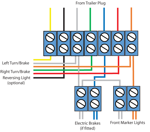
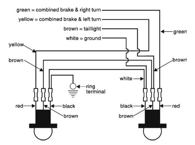
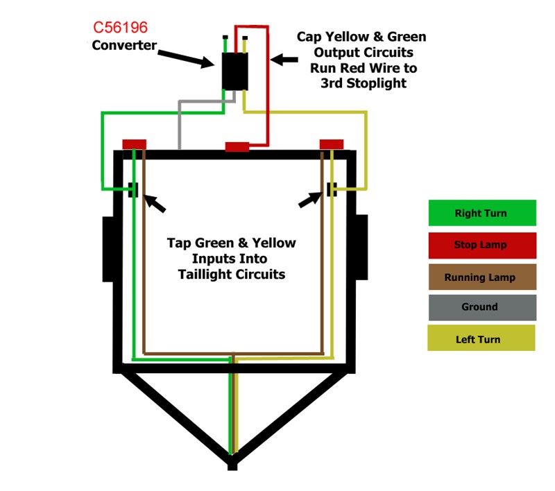
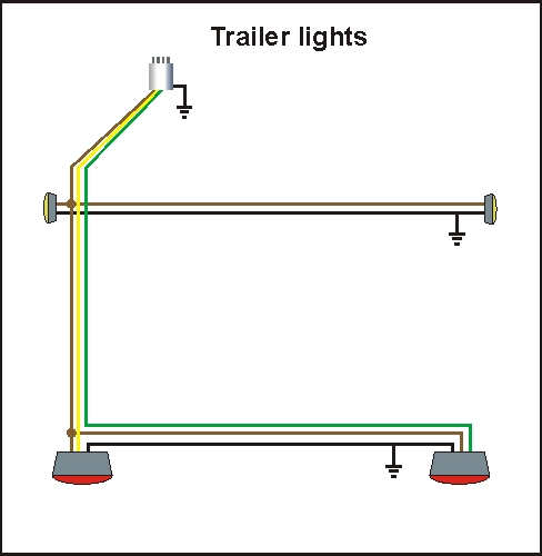
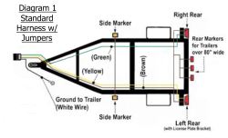
On most recreational vehicles. Diagram 1 shows a traditional wiring layout with jumper wires to provide running light functions for both sides of the trailer and diagram 2 shows a wishbone.

Utility Trailer Lights Wiring Diagram Wind Giant
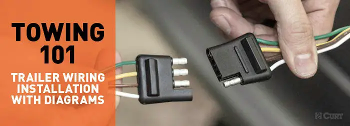
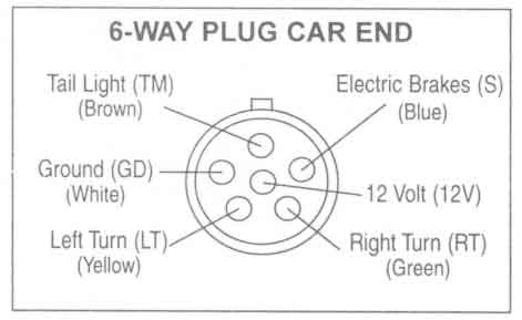
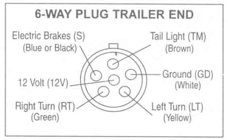
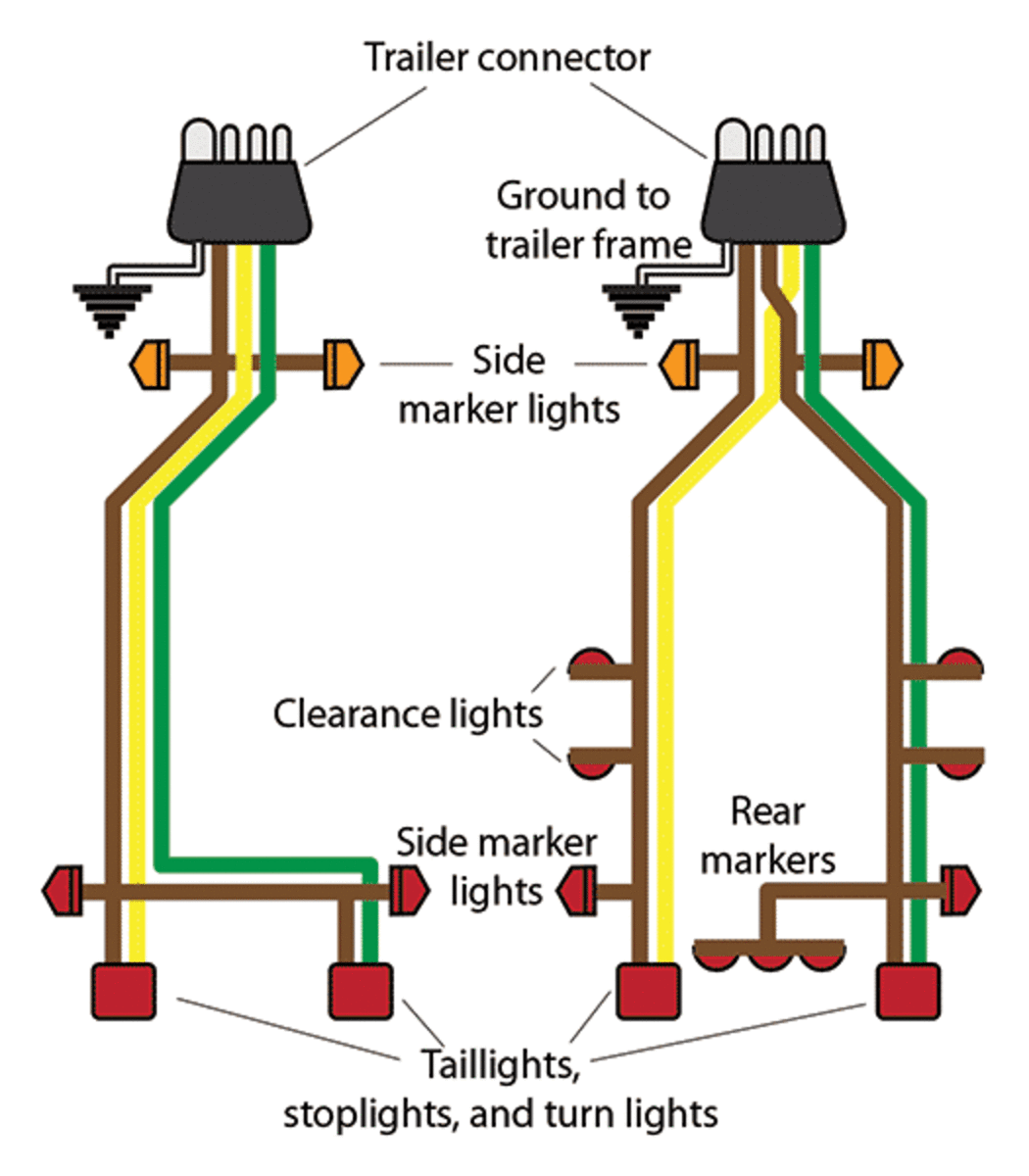
Utility trailer light wiring diagram. 4 way trailer connectors are. 7 way trailer wiring diagram is explained in details in the picture and the table below. The four wires control the turn signals brake lights and taillights or running lights. As the name implies they use four wires to carry out the vital lighting functions. We recommend these standards because they are pretty universal. The following trailer wiring diagrams and explanations are a cross between an electrical schematic and wiring on a trailer.
Trailer light wiring basics it will help to have an understanding of trailer light systems and we recommend reviewing trailer wiring diagrams before starting this project. Though trailer lighting systems are available in an array of configurations the most popular is the 4 way system. That said for specific situations there are industrial standards with different connectors and wire arrangements. I have attached two basic trailer light wiring diagrams of utility trailers for you to check out. Large 5th wheel trailers. The difference between the two diagrams is the type of wiring harness that is being used.
They also provide a wire for a ground connection. 4 way trailer connectors are typically used on small trailers such as boat snowmobile utility and other trailers that that do not use brakes. 7 pin trailer wiring diagram with brakes. 7 way trailer connectors are used by the following vehicle types.
