Uv light can cause color changes or structural degradation of plastics rubber paper and other non metallic materials used in the hvac system. In this project we will go over how to build an ultraviolent uv led circuit.

Learn About Koi Pond Filtering Uv Filters And Pumps Skagitek
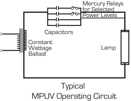
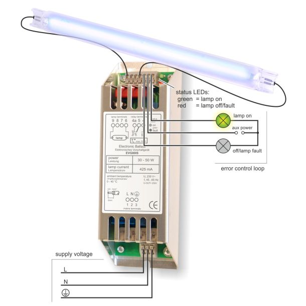
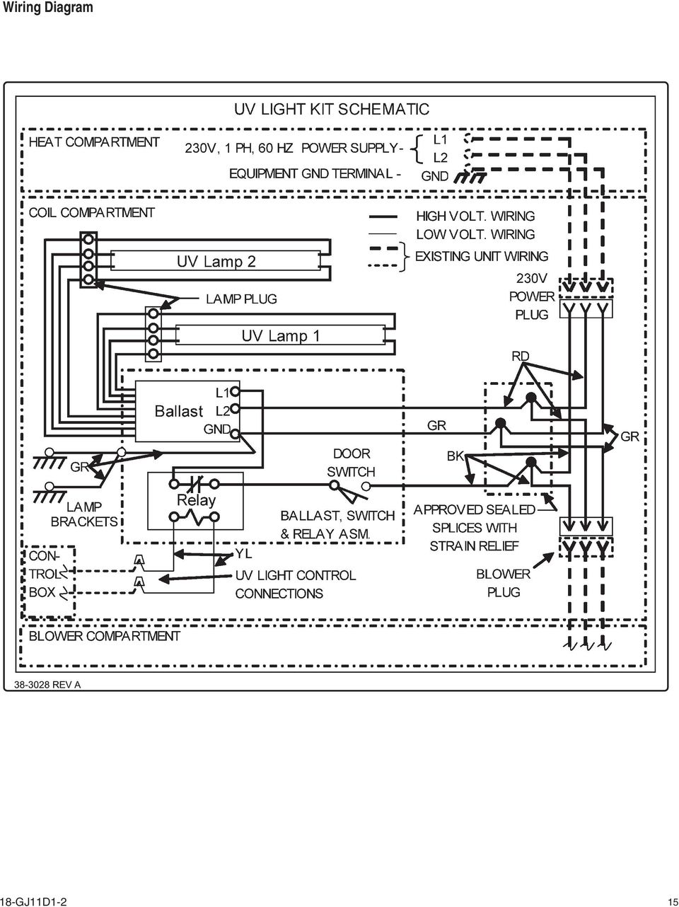
Uv light wiring diagram. Install lamp in location that prevents exposure of plastics rubber paper and other non metallic materials to uv light or shield such materials with aluminum tape sheet metal or metal conduit. Use the wiring diagrams below to connect to power. Small pond pumpfilter although many other pond filters such as the supreme pond master 1000 can be adapted this way as well. Germicidal uv light installation instructions blue tube uv mounting options blue tube uv is installed inside the air handling system to reduce. Its a very simple circuit only requiring a uv led a resistor and a power source either a dc power supply or a 3 aa batteries. This diagram shows a pond uv clarifier connection using the bypassdiverter valve common to many fountains and simple aquarium filters.
The hot and neutral terminals on each fixture are spliced with a pigtail to the circuit wires which then continue on to the next light. How to build an ultraviolent uv led circuit. Different electrical symbols are used to make the wiring diagram below. Starters cylinder fs 2 starters. This is a circuit which powers a uv led so that it gives off its uv light. The high voltage 120.
For a magnetic ballaststarter wiring diagram please click this link. The source is at sw1 and 2 wire cable runs from there to the fixtures. From the junction box the neutral wire is not taken out to the switch board rather it is taken out from the junction box and. Multiple light wiring diagram. The filter pictured here is a via aqua bh 2000ad. Germicidal ultraviolet uv c applications wiring diagrams view the wiring diagrams for ballasts 10 0091 10 0127 10 0136 10 0137 10 0155 10 0201 10 0210 below or download a pdf ballast specification sheet which includes the ballast specs photos lamp types and wiring diagrams.
This diagram illustrates wiring for one switch to control 2 or more lights. The low voltage power supply 18 to 32 vac is marked er. Wiring diagram of single tube light installation with electromagnetic ballast. How to install a single tube light with electromagnetic ballast. Ballaststarterlight wiring diagram via aqua terminator electronic ballast 3899 jump to shopping cart self starting 5 watt ballast 9 watt ballast may be used similar compact uv sterilizers does not include wiring.


