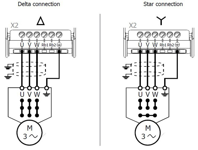
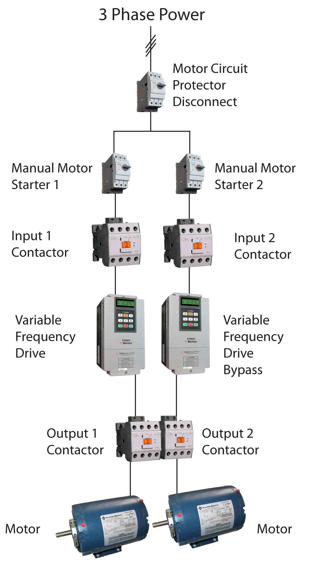
Set in vfd parameters motor data as follows. Learn the basic wiring of variable frequency drives vfd with our electrician steve quist.
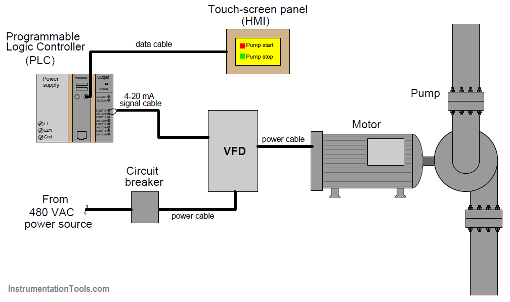
Controlling 3 Phase Induction Motor Using Vfd And Plc
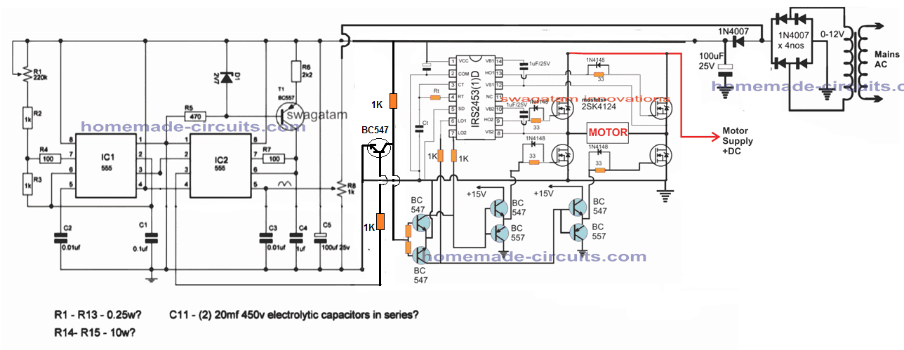
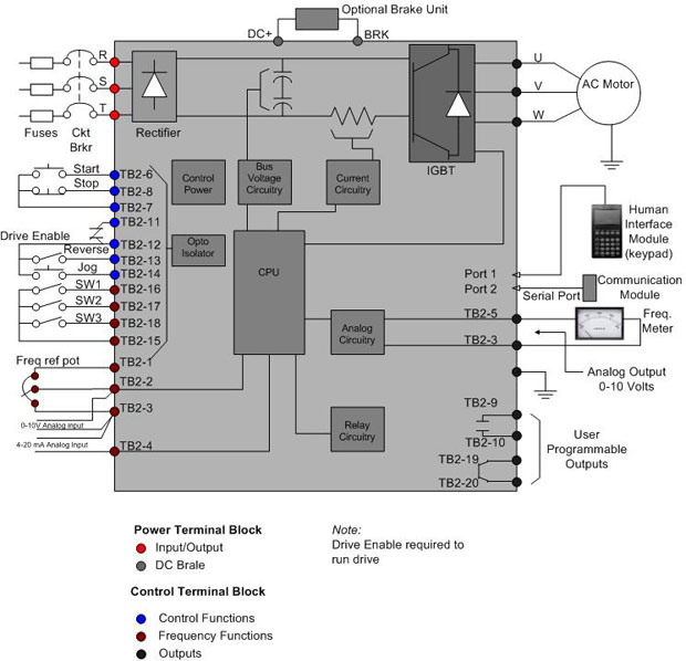
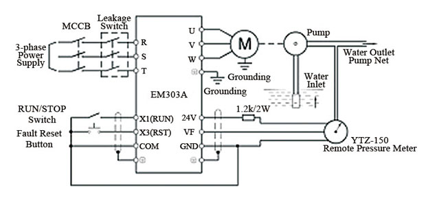
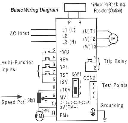
Vfd connection diagram with motor. Do different function on motor operation like jog accedeacc time taking feed back up. Vfd variable frequency drive used for 1. The vfds showed in the video are the d720s 230v single phase and the d720 230v three phase. Switch on the 3 phase power supply. Pin out connection diagram for vfd m fig. Vfd start stop wiring diagram.
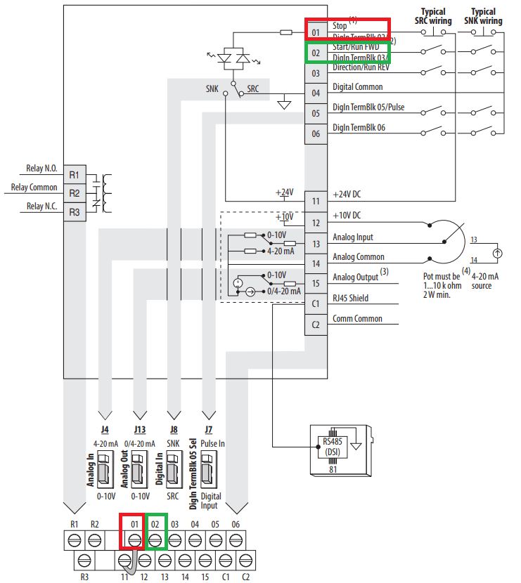
Motor rated voltage 400 v motor rated frequency 87 hz. Vfd is a short form of variable frequency drive or variable voltage variable frequency drivethe vfds are working based on changing the input frequency and input voltage of the motor we can change the speed of the. Change speed of motor 3 phase 2. Motor develop constant rated torque from low. In this video we used the very popular mitsubishi d700 series vfd showing single phase and three phase wiring instructions. I am here with giving you a vfd start stop wiring diagram for running a vfd through panel board push button and keypad of the vfd it is called hmi.
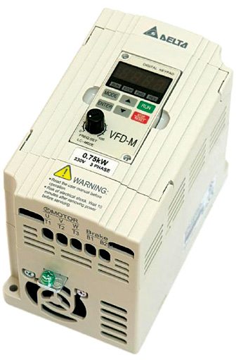
Vf line comes through rated motor point 230 v 50 hz to maximum point 400 v 87 hz with correct ratio. For programming the vfd m. Rated vfd output current not less than motor current in delta connection. Change direction of motor 3. We strongly recommend using a certified electrician to set up your vfds. Controlling a digital keypad on delta vfd m steps for complete motor control.
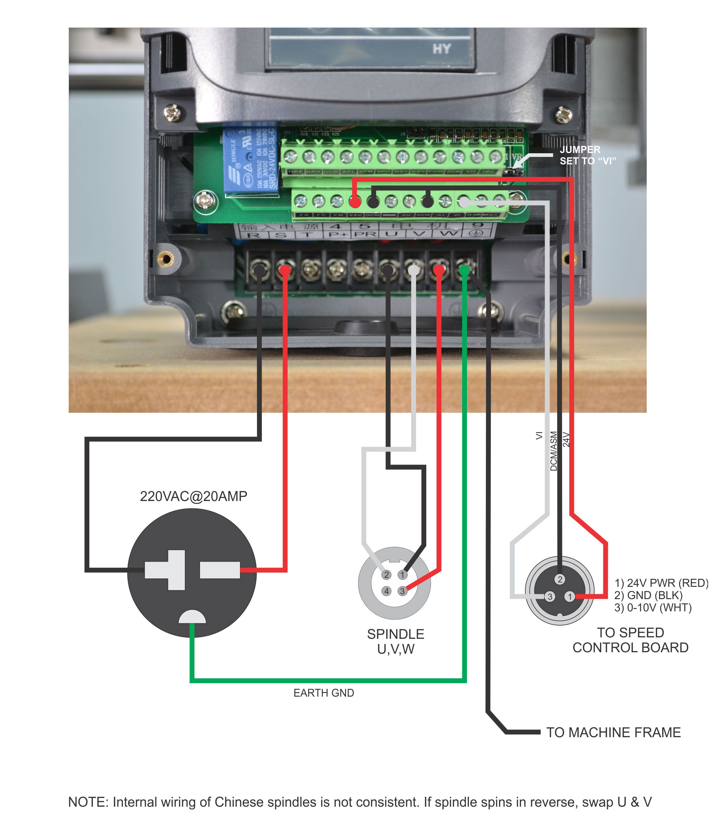
Check connections of l1 l2 l3. 1 the vfds three phase ac input terminals rl1 sl2 tl3 the power lines input terminals connect to 3 phase ac power through line protection or leakage protection breaker it does not need to consider the connection of phase sequence. Main circuit wiring the vfd main circuit terminals shown as below figure. T1 t2 t3 used for giving 3 phase input to vfd and connecting motor to it and wires coming out of m0 m1 and gnd.
