Dc regulator circuit diagram. Many schematic diagrams show only the control circuit.

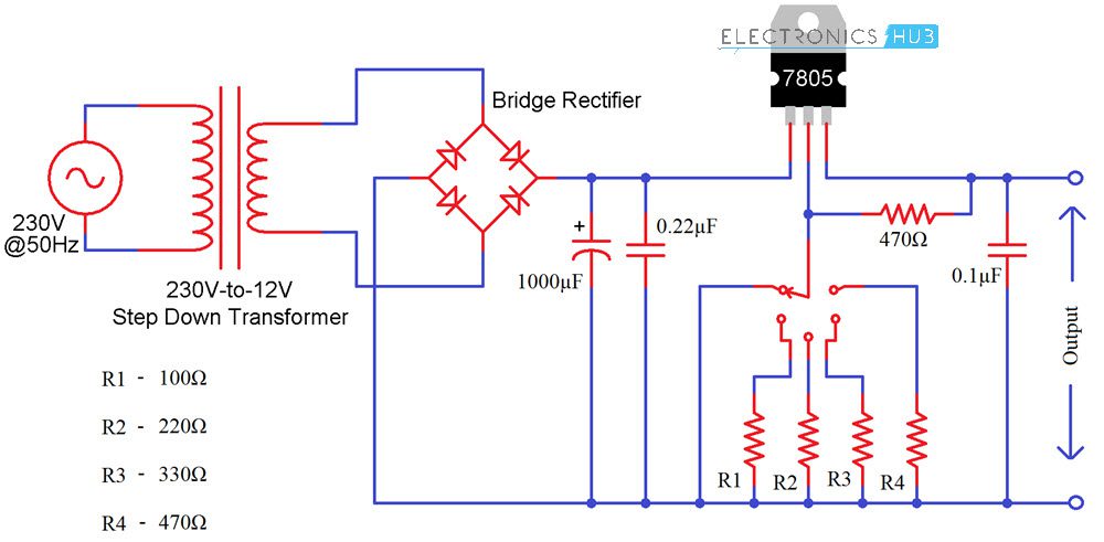
7805 Adjustable Voltage Regulator Circuit Eleccircuit Com
Voltage control circuit diagram. The first circuit to be discussed is a basic control circuit used throughout industry. The output of a2 is a square wave signal with a constant frequency of around 200 hertz. 0040 ohm n channel power mosfet. This creates the same brightness from the led as a constant dc voltage while needing less than 50 of the energy enabling a single 12 volt cell to be used. Here is a schematic diagram for a simple circuit that uses a 9 vdc circuit with a handheld pushbutton to turn a 120 vac lamp on and off. How to use relays to control electronic line voltage circuits.
Voltage monitoring circuit for 12 volt lipo battery pack schematic circuit diagram tda7293 100w rms amplifier schematic circuit diagram ps1502d 0 15v adjustable 15v 72v stage power supply schematic circuit diagtram. The circuit doesnt deliver a dc voltage to the led but a high frequency pulse. But here in this video i use 35 voltage. The ic a2 following it functions as a simple comparator. The entire circuit is powered with rectified dc supply but the regulated power is connected to timers and unregulated power is connected to potentiometers to get the variable voltage. Series double triode voltage regulator circuit diagram.
This schematic shows both the control circuit and the motor circuit. Jun 30 2020 explore juni joness board circuit diagram on pinterest. These transformers use a tank circuit composed of a high voltage resonant winding and a capacitor to produce a nearly constant average output voltage with a varying input current or varying load. This signal has a variable pulse width from 0 to 100. The ferroresonant transformer ferroresonant regulator or constant voltage transformer is a type of saturating transformer used as a voltage regulator. Schematic diagrams do not always show both control and motor connections.
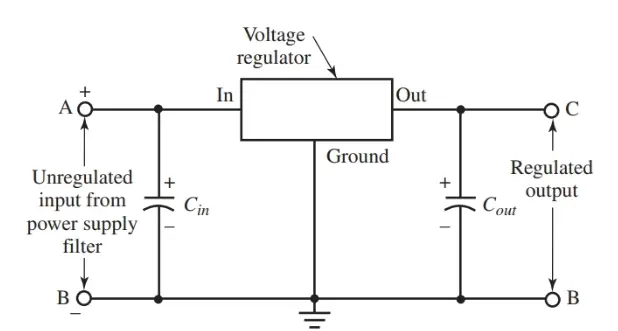
A reference voltage is fed to the inverting input of the a2 ic via the potentiometer p1. This is only dc voltage regulator. Ic voltage regulator circuit diagram. Figure 914 shows a start stop push button circuit. By doug lowe. There are basically four types of ic voltage regulators hence i will show you the circuit diagram of each one of these separately.
We can control 0 voltage to 100 voltage. Both the timers are configured to work as comparators ie as long as the input present at the pin2 of timer is less positive than 13 vcc then the. Series triode voltage regulator circuit diagram. Over voltage protection using timers circuit operation. The relay in the circuit has a coil rated for 9 vdc and a switch rating of 10 a at 117 vac. This is a voltage controller circuit with ampere using irf540n.
This circuit increases the voltage so the 12 volt batteries will power the ultra bright leds. Thus only 9 vdc passes through the. Fixed positive voltage regulator circuit diagram. See more ideas about circuit diagram circuit electronics circuit. Voltage controller circuit with ampere using irf540n. This transistor can take 33amperes and 100voltage.
Gallery of Voltage Control Circuit Diagram