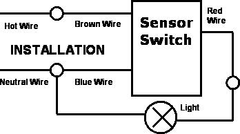
If the light switch has a ground screw on it usually green and at the bottom of the switch connect it now. Assuming it is a steel box.

Ka 6896 Day Night Switch Wiring Diagram Free Diagram
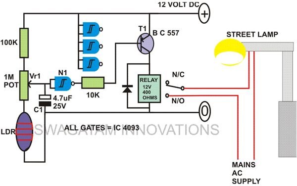
Wiring a day night switch. 1 light activated day night switch using transistors. First of all we should connect the ground wires to the box. The source is at sw1 and the hot wire is connected to one of the terminals there. If the lights remain on with the switch off highly doubtful you have something messed up. Should be the same as any other switch you should only have to run the hot to it and switch the hot you only ever switch the hot. This small day night switch can switch on any electrical device automatically when dark falls and switch off in the morning automatically.
In this diagram 2 wire cable runs between sw1 and the outlet. The light switch should always remain in the on position for the photocell to operate automatically. How is the day night switch connected to the lights. You may like it too. Just install this smart ldr dusk to dawn sensor twilight switch at your home office warehouse factory or farm and watch your electricity bills cut down. This is commonly used to turn a table lamp on and off when entering a room.
What i know is the wires will always have power but the switch is the one that regulates the flow of electricity to pass or not to pass to the lights. I am going to share an automatic daylight sensor switch project. Turn the light switch off first to make sure the lights do in fact turn off to isolate the problem to the wiring at the photocell or the photocell itself. With the power coming to the switch and then going to the lights you will notice that there are two black wires two white wires and two ground wires bare wires. I want to control an air pump looked like this projects to works only daylight hoursto save electricity and help extend the use of the air pump. Wiring a switch to a wall outlet.
The first diagram shows how the circuit can be configured using transistors the second and the third circuits demonstare the principle by using cmos ics while the last circuit explaines the same concept being implemented using the ubiquitous ic 555. Here a receptacle outlet is controlled with a single pole switch.


