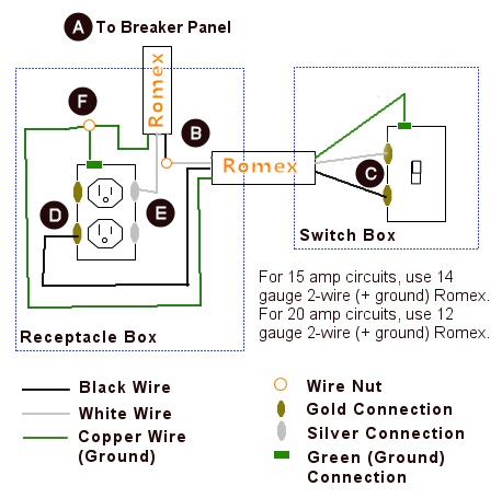
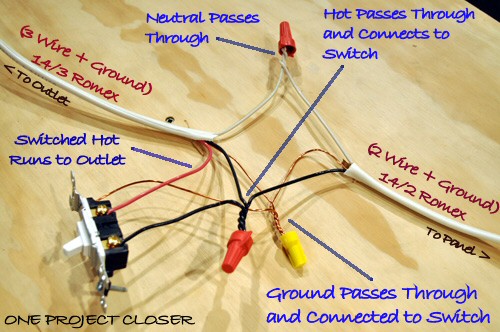
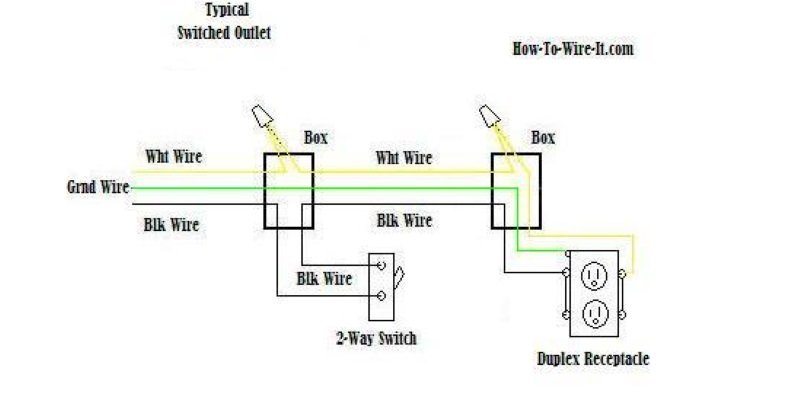
Wiring diagram of a switched electrical receptacle outlet and an unswitched electrical receptacle outlet with the power entering the switched outlet electrical box from the circuit breaker panel. The hot source wire is removed from the receptacle and spliced to the red wire running to the switch.

Question Re Wiring March Pumps To Switches
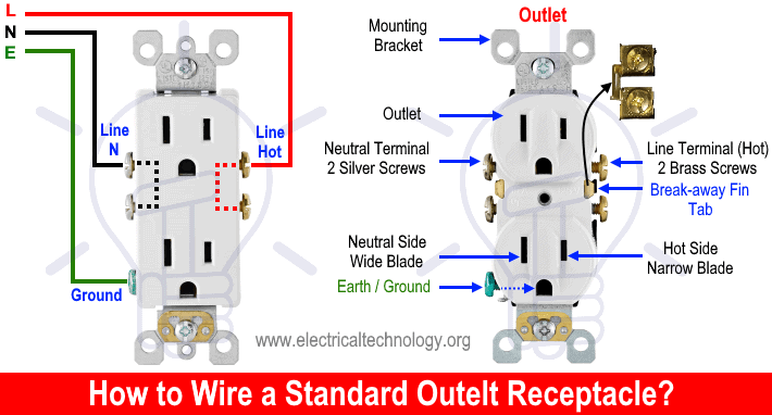
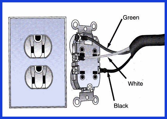
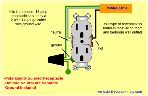
Wiring diagram for an outlet. Wiring an outlet to a switch loop. This is a standard 15 amp 120 volt wall receptacle outlet wiring diagram. A grounded contact at the bottom center is crescent shaped. It means all the connected loads to the load terminals of gfci are protected. This wiring diagram illustrates adding wiring for a light switch to control an existing wall outlet. This is a polarized device.
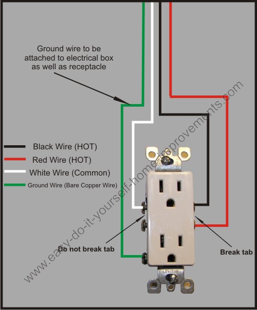
Wiring a gfci combo switchoutlet with protected light outlet receptacle. Multiple outlet in serie wiring diagram. The diagram above shows 2 outlets wired in series and more outlets can be added to this circuit by wiring the 2nd outlet just like the 1st outlet to keep the circuit continuing on until you end the circuit at the last outlet. In the diagram below a 2 wire nm cable supplies line voltage from the electrical panel to the first receptacle outlet boxthe black wire line and white neutral connect to the receptacle terminals and another 2 wire nm that travels to the next receptacle. Any break or malfunction in one outlet will cause all the other outlets to fail. The light onoff operation can be controlled through the gfci switch while the ordinary outlet is directly connected to the gfci load terminals.
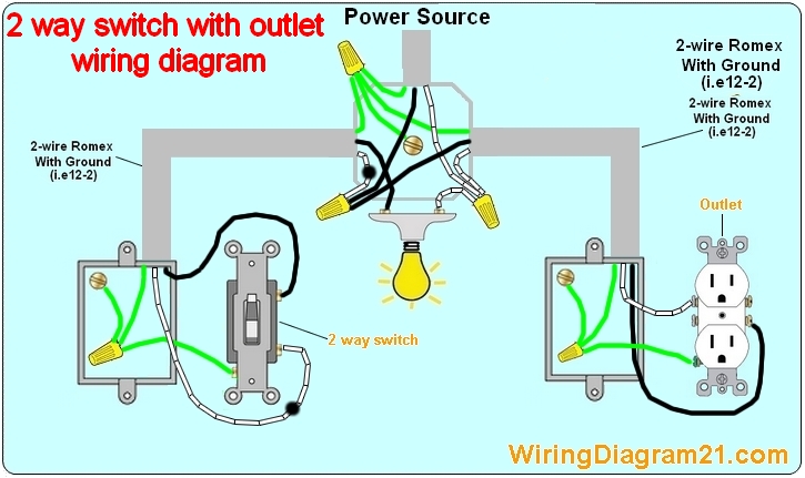
The diagram below shows the power entering the circuit at the grounded outlet box location then sending power up to the switch and a switched leg back down to the outlet. For wiring in series the terminal screws are the means for passing voltage from one receptacle to another. However working on your circuit breaker box and electrical system can lead to serious injury or death if you dont know what youre doing so hire an electrician if you don. In this gfci outlet wiring and installation diagram the combo switch outlet spst single way switch and ordinary outlet is connected to the load side of gfci. Multiple outlet in parallel wiring diagram. Wiring a grounded duplex receptacle outlet.
Dont use this receptacle when no ground wire is. These electrical wiring diagrams show typical connections. Wiring a new 220 outlet is a project that someone who has experience working with electricity can do safely by working carefully and following the proper precautions. The long slot on the left is the neutral contact and the short slot is the hot contact. In this special case wiring diagram both light and ordinary outlet is connected to the load terminals of gfci. The single pole switch has a neutral conductor for future electronic controls such as a timer or a wifi switch.
Wiring a gfci outlet with combo switch outlet receptacle light switch. Now some electricians will use a 1wire jumper from the outlet and wire nut together the circuits inside the box but. The source is at the outlet and a switch loop is added to a new switch.
Gallery of Wiring Diagram For An Outlet