Return to the duplex cable under the hood where the brake wire now white needs to be separated from the 12 volt hot lead black. Drive a crew cab extended cab with long bed cargo van or extended length suv extra wire etbcxw sold separately will make installation much easier.

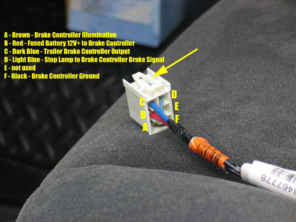
Part1 How To Wire Fj Cruiser With Electronic Brake Controller 7 Pin Tow Adapter Tow Wire Diagram
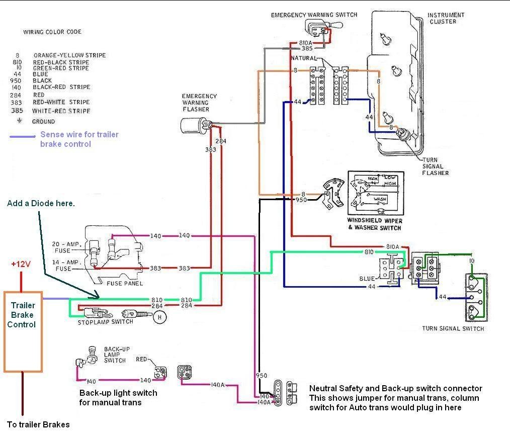
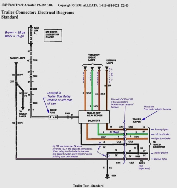
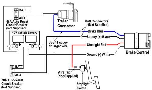
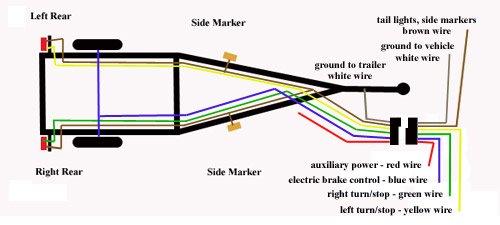
Wiring diagram for electric trailer brake controller. Collection of prodigy brake controller wiring diagram. Ensure it is sealed off and cannot create a short circuit with any other wire or the chassis. A wiring diagram is a streamlined conventional pictorial representation of an electric circuit. This universal wiring kit lets you install an electric brake controller sold separately in your vehicle and a 7 way connector for your trailer lights at the same time. It reveals the parts of the circuit as streamlined forms as well as the power and signal connections in between the gadgets. Elecbrakes must be connected to trailer wiring circuits as outlined in the wiring diagram.
Primus brake controller wiring diagram nov 16 horbar. You almost certainly know already that primus brake controller wiring diagram is among the top issues online. Secure the brake controller into the mounting bracket. It shows the elements of the circuit as simplified forms as well as the power and also signal connections between the devices. Assortment of electric trailer brake wiring schematic. The four wires on the brake controller will be connected shortly.
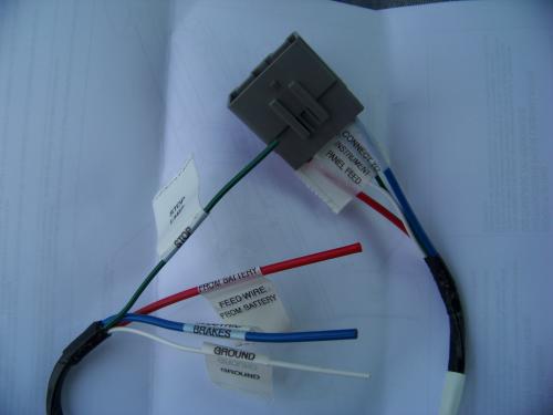
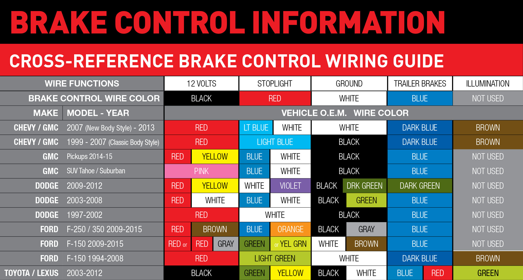
The service brake circuit must be disconnected from an existing trailer plug. Wiring the 7 way trailer connector and brake controller. Following the wiring diagram included with the controller run the blue wire through the firewall and to the rear of the vehicle where it will connect to the trailer connector. A wiring diagram is a simplified traditional photographic depiction of an electrical circuit. Plugs into the existing 4 way.
