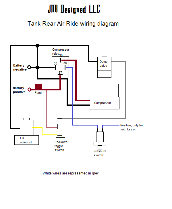
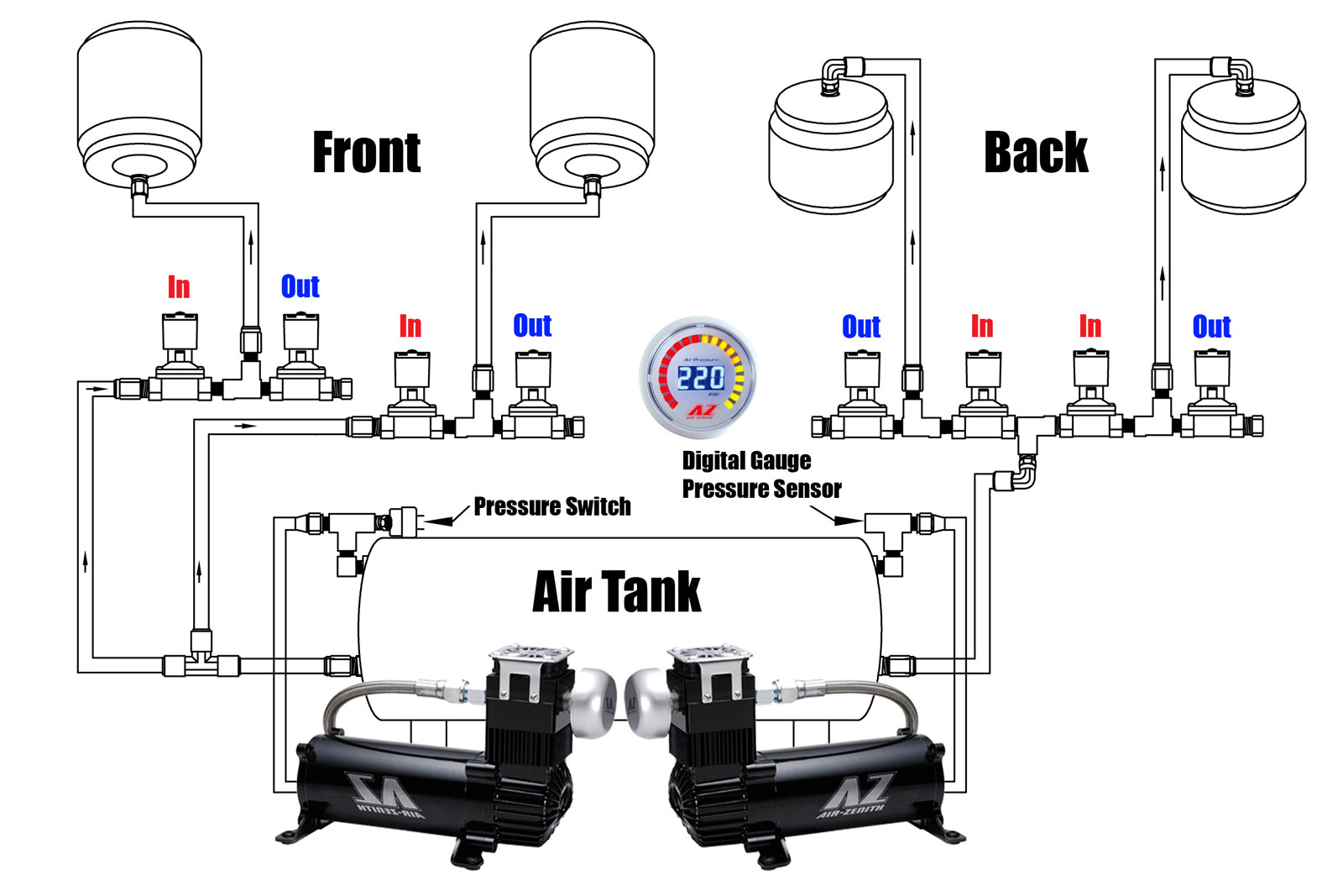
We give a brief explanation here on wiring two ver y common pressure switches found on many electric air. Collection of pressure switch wiring diagram air compressor.

High Output Compressors 101 Air Zenith Compressor Mounting
Wiring diagram for pressure switch on air compressor. The switch may be wired correctly yet if a full path the motor allows the compressor to cut in when the pressure is low cut out when the pressure is at the stopping point the compressor stops and thats repeatable without the switch in the circuit and then when you add the switch there doesnt appear to be enough power to drive the. This is a short video on how to wire a pressure switch on an electric air compressor. Variety of air compressor pressure switch wiring diagram. The video below speaks to these problems and aims to demonstrate the correct way to wire to a pressure switch. In this video we show you the best way to a pressure switch for 115v and 230v pumps. It shows the components of the circuit as streamlined shapes as well as the power and also signal links between the devices.
This method will work for any pump that runs directly off of a pressure switch including jet pumps well. A wiring diagram is a simplified conventional photographic depiction of an electrical circuit. If you have any questions please feel free to comment below email us or call one of our fire protection air compressor experts at 800 345 8207. A wiring diagram is a simplified traditional pictorial depiction of an electric circuit. Properly wire your air compressors pressure switch. It reveals the parts of the circuit as simplified forms as well as the power and also signal connections between the tools.


