Residential power is usually in the form of 110 to 120 volts or 220 to 240 volts. Single phase motors are used to power everything from fans to shop tools to air conditioners.

240v Single Phase Motor Wiring Diagram Wiring Diagram And
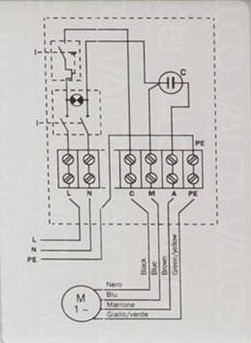
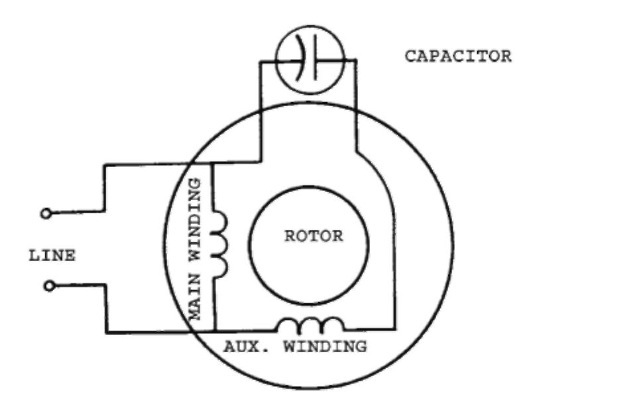
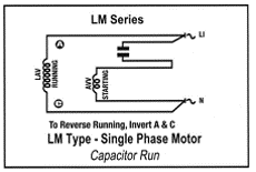
Wiring diagram of single phase motor. Wiring a motor for 230 volts is the same as wiring for 220 or 240 volts. Variety of single phase motor wiring diagram forward reverse. A wiring diagram is a simplified conventional pictorial representation of an electrical circuit. Wiring diagram single phase motors 1empc permanent capacitor motors 1empcc capacitor start capacitor run motors electric motors limited when a change of direction of rotation is required and a change over switch is to be used it will be necessary to reconnect the termination on the terminal block. Capacitor start capacitor run induction motors are single phase induction motors that have a capacitor in the start winding and in the run winding as shown in figure 12 and 13 wiring diagram. Each component ought to be placed and linked to different parts in particular manner.
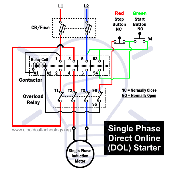
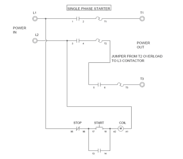
The above diagram is a complete method of single phase motor wiring with circuit breaker and contactor. This type of motor is designed to provide strong starting torque and strong running for applications such as large water pumps. Single phase motor wiring diagram with capacitor baldor single phase motor wiring diagram with capacitor single phase fan motor wiring diagram with capacitor single phase motor connection diagram with capacitor every electrical arrangement is made up of various unique pieces. In the above one phase motor wiring i first connect a 2 pole circuit breaker and after that i connect the supply to motor starter and then i do cont actor coil wiring with normally close push button switch and normally open push button switch and in last i do connection between capacitor.

.png)


