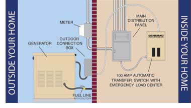
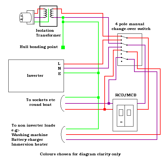
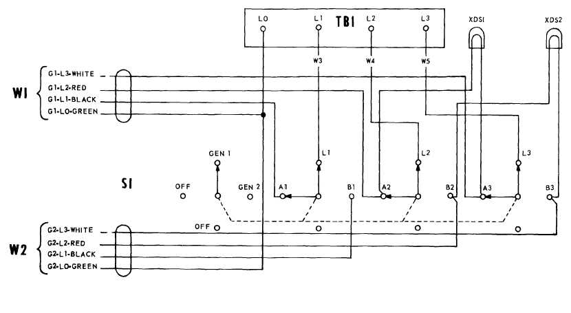
Assortment of manual transfer switch wiring diagram. It reveals the components of the circuit as streamlined forms and also the power as well as signal connections in between the gadgets.
Manual Transfer Switch Generator Manual Transfer Switch
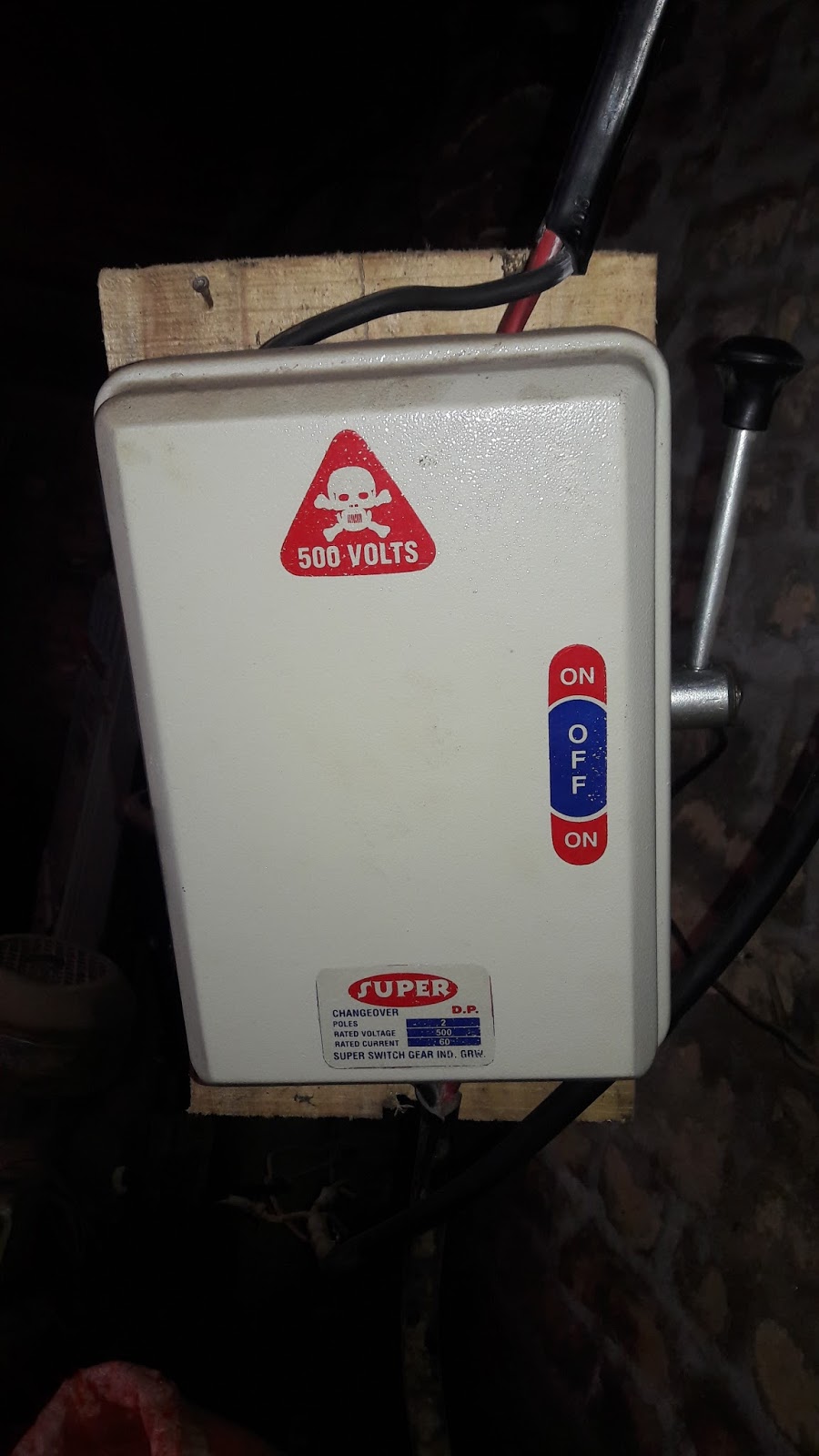
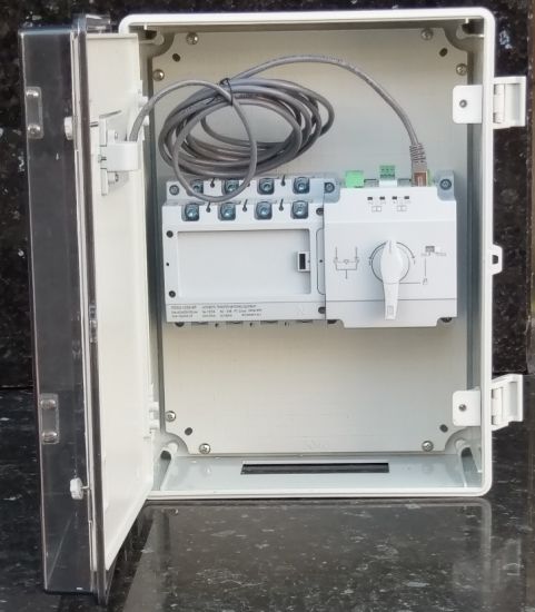
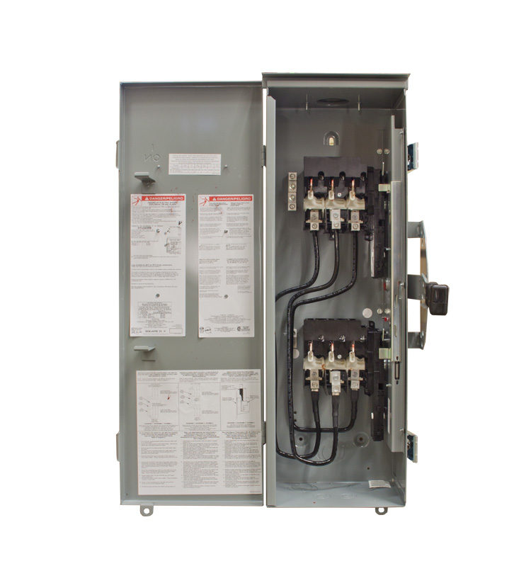
1 phase manual changeover switch wiring diagram. This post i will shown the complete method of manual or handle change over switch the knob type manual changeover switch wiring same like handle change over switch and its just like a voltmeter sector switch. Manual changeover switch connection duration. 6 control wiring single phase sno itemdescription model imaxamps mountingstyle 1 manualchangeover16asinglepolen mco16s 16 panelwallmounted 2 manualchangeover32asinglepolen mco32s 32 panelwallmounted 3 manualchangeover40asinglepolen mco40s 40 panelwallmounted 4 manualchangeover63asinglepolen mco63s 63 panelwall. In this methods of wiring the battery and ups has been connected directly to the main supply where the output of the ups has been connected to the partial load specific appliances where we need continues power supply in case of power failure with the help of two pole single phase manual changeover switch. In fig 2 different connection and wiring diagrams are shown for a two pole single phase manual changeover switch. A wiring diagram is a simplified traditional pictorial representation of an electrical circuit.
The upper portion of the changeover switch is directly connected to the main power supply while the lower first and right connections slots are connected to the backup power supply like generator or inverter. How to wire a single phase generator change over switch. Manual changeover switch are mostly use in 2 types in which one have the move able knob and 2nd one the handle changeover switch. Single phase electricity explained wiring diagram energy meter duration.


