What is dol starter. I am facing problem of operation of dol starter 3 phase 3 hp motor through plc.

Three Phase Dol Starter Wiring Diagram With Mccb Contactor
3 phase dol starter wiring diagram pdf. And one wiring is called controlling wiring. A2 14 18. I have 24vdc coil 5 amp resistive load on 8 qty connected to my plc card this is smoke extraction system and there are five zone with five different plc installed each zone has eight 3hp fans working in primary and secondary configuration. Assortment of 3 phase motor starter wiring diagram pdf. The connection of contactor can be done among relay coil supply voltage as well as thermal overload. Dol starter control diagram three phase.
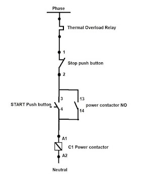
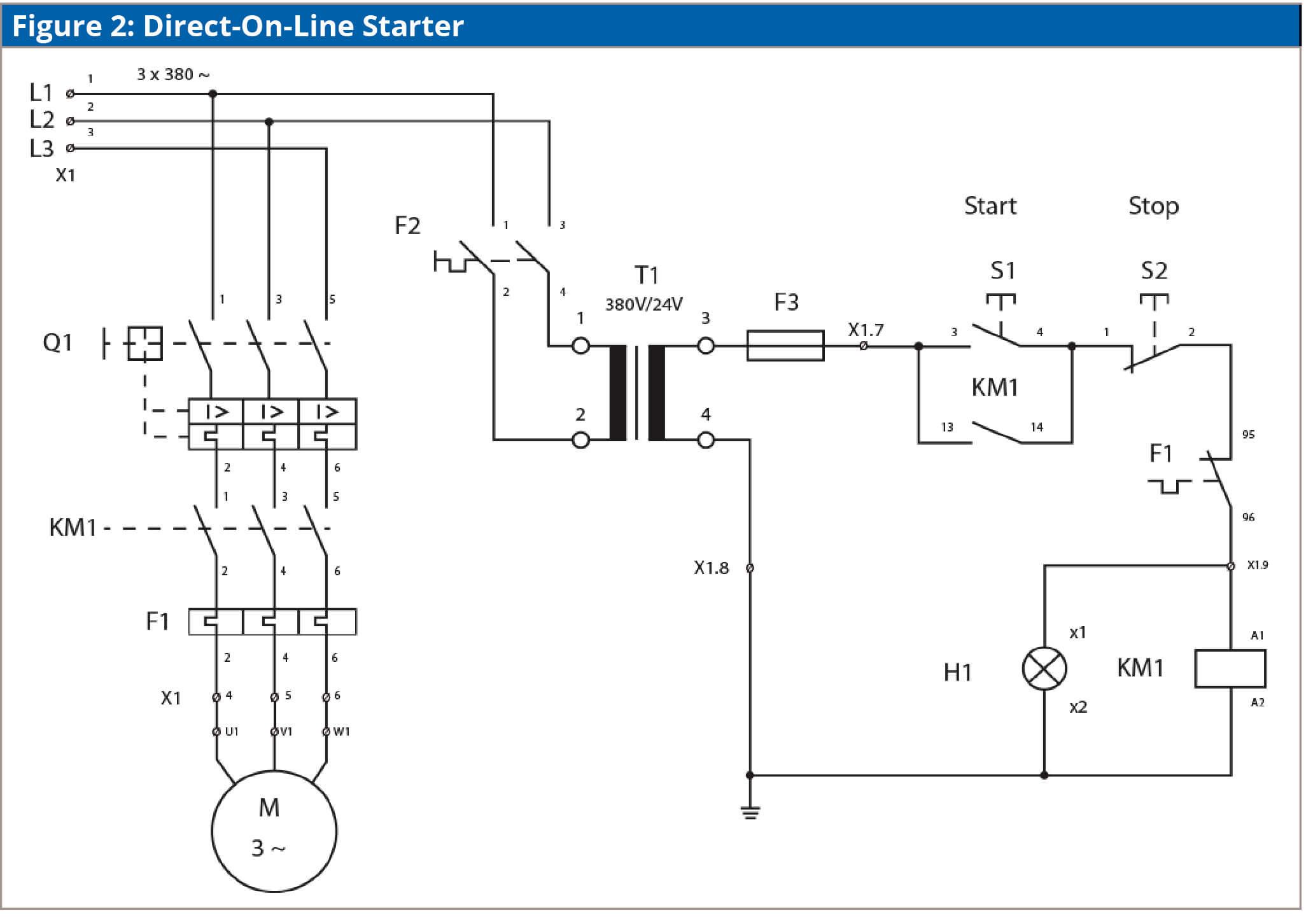
A dol starter is a direct on line motor starter. A wiring diagram is a streamlined standard pictorial representation of an electric circuit. The wiring of direct on line control circuit starter is following. A dol starter or direct on line starter or across the line starter is a method of starting of a 3 phase induction motorin dol starter an induction motor is connected directly across its 3 phase supply and the dol starter applies the full line voltage to the motor terminals. In the below dol starter wiring diagram i shown a molded case circuit breaker a magnetic contactor normally open push button normally close push button switch thermal overload relay motor trip indicator and 3 phase motor. It shows the parts of the circuit as simplified shapes and also the power and also signal links in between the tools.
A wiring diagram is a streamlined conventional photographic representation of an electrical circuit. Eaton wiring manual 0611 8 1 88 all about motors page motor protection 8 3 notes on engineering 8 15 circuit documents 8 19 power supply 8 21 control circuit supply 8 24 contactor markings 8 25 direct on line start of three phase motors 8 26 control circuit devices for direct on line start 8 34 star delta switching of three phase motors 8 35. Assortment of motor starter wiring diagram pdf. In the above three phase dol starter wiring diagram. It shows the elements of the circuit as streamlined shapes and the power and signal links in between the tools. The l1 contactor is connected from normally open no to r phase using mccb.
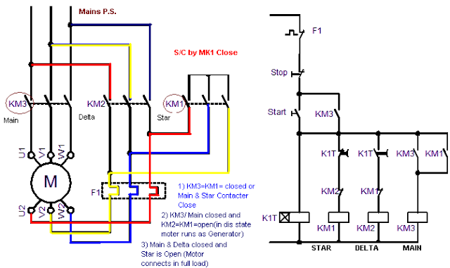
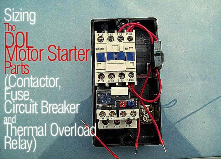
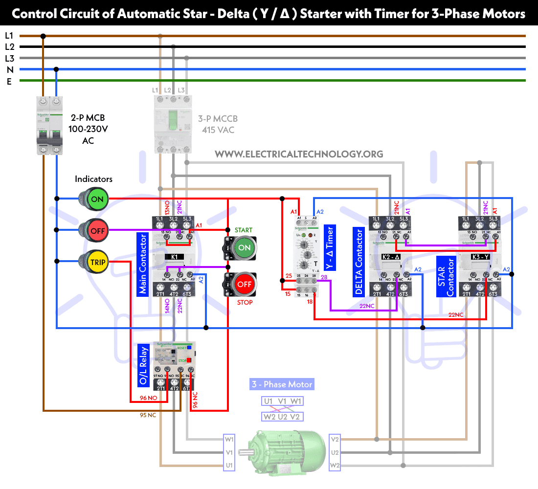
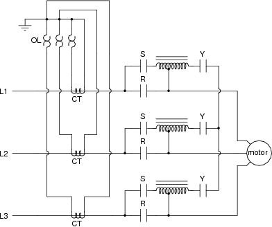
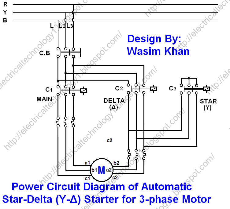
13 17 with a flying lead to be connected to overload terminal 95. In this tutorial we will show the star delta y δ 3 phase induction ac motor starting method by automatic star delta starter with timer with schematic power control and wiring diagram as well as how star delta starter works and their applications with advantages and disadvantages. All other control and power connections have to be made by the installer. Sometimes known as an across the line starter this type of motor controller is used as a simple starter for larger electric motors providing. 1 the following links are pre fitted to the starter. Wiring of the direct on line dol motor starter 1 three phase supply 230volt coil see wiring diagram.
Despite this direct connection no harm is done to the motor.
