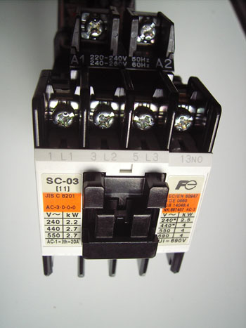
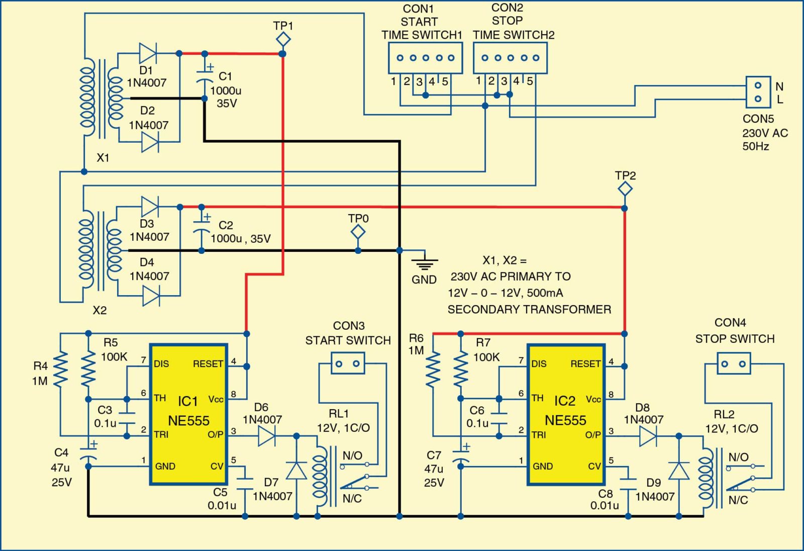
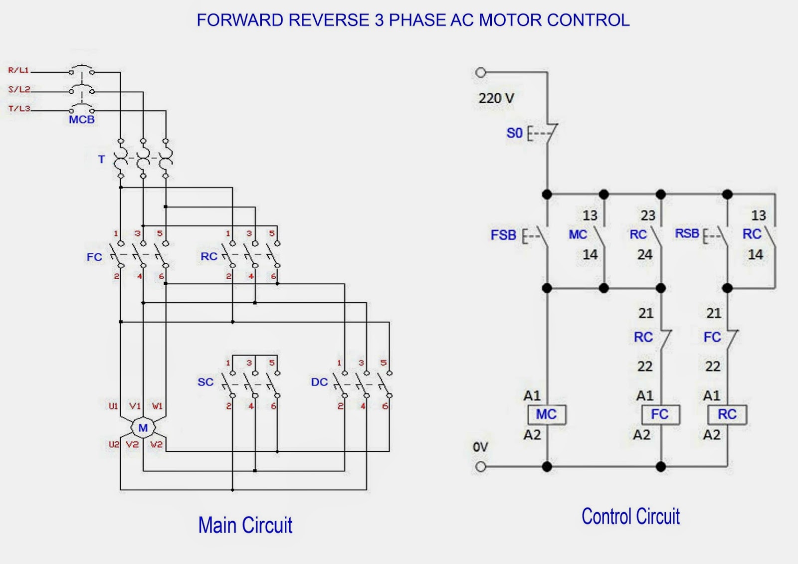
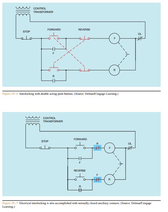
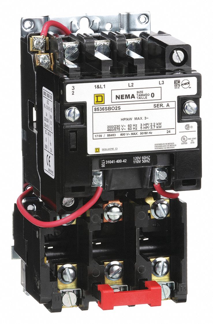
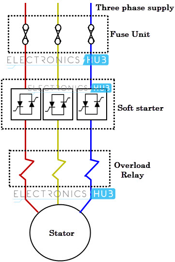
The motors starter wires directly to the motors wire terminals. It reveals the parts of the circuit as simplified shapes and the power as well as signal links between the gadgets.
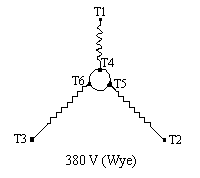
Part Winding
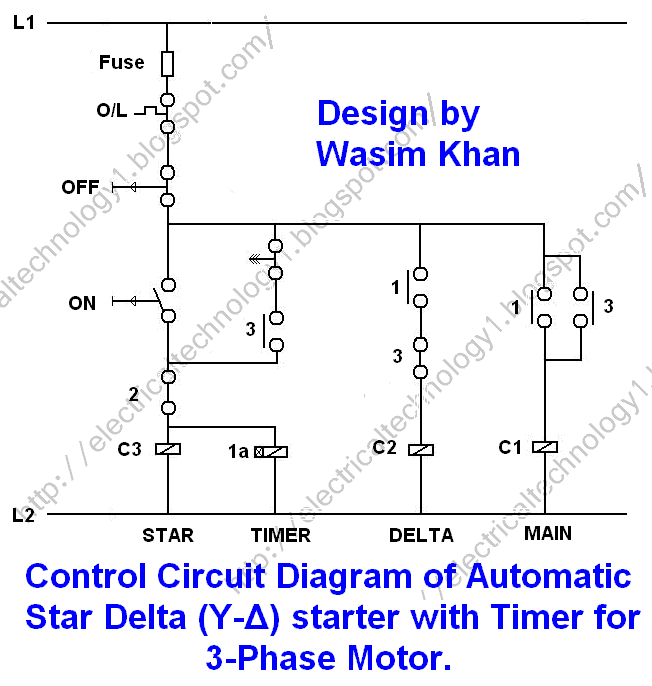
3 phase electric motor starter wiring diagram. On abb contactor wiring diagram. Time lapse of schematic diagram drawn into a wire diagram and the wiring of the magnetic motor starter. The following diagram is shown for 3 phase motor control of a delta star connection. It uses three contactors an overload relay one auxiliary contact block a normally open start pushbutton a normally closed stop pushbutton an on delay timer of 0 20 seconds and a power supply with a fuse. To use three phase electricity a motor needs windings spaced 120 degrees apart. Different regions may use different voltages.
Variety of 3 phase motor starter wiring diagram. It reveals the elements of the circuit as streamlined forms and the power and signal connections between the tools. Start stop 3 wire control. They can also be found in large residential complexes and appliances requiring a large amount of power. Refer to the motor manufacturers data on the motor for wiring diagrams on standard frame ex e ex d etc. Three phase electric motors use three different electric legs with a 13 cycle lag between them.
Starting a three phase motor. Collection of 3 phase electric motor starter wiring diagram. Although these systems may seem intimidating at first a walkthrough on 3 phase wiring for dummies will help clarify the whole situation. A wiring diagram is a simplified standard photographic depiction of an electric circuit. Three phase systems are extremely common in industrial and commercial settings. W2 cj2 ui vi wi w2 cj2 ui vi wi a cow voltage y high voltage z t4 til t12 10 til t4 t5 ali l2 t12 ti blu t2 wht t3org t4 yel t5 blk t6 gry t7 pnk.
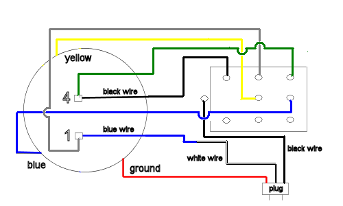
28 images residential electrical wiring diagrams wiring diagram schematic diagram of electric motor wiring diagram and 25 best ideas about electrical wiring diagram on 25 best ideas about. Capacitor motor single phase wiring diagrams always use wiring diagram supplied on motor nameplate. A wiring diagram is a streamlined conventional pictorial depiction of an electrical circuit. Wye delta open transition 3 phase motors. The above diagram is a complete method of single phase motor wiring with circuit breaker and contactor. I had to do this a few times with floodlights to be used outside.
In the above one phase motor wiring i first connect a 2 pole circuit breaker and after that i connect the supply to motor starter and then i do cont actor coil wiring with normally close push button switch and normally open push button switch and in last i do connection between capacitor. 33 l1 l2 l3 n suggested wiring arrangement selector switch hi speed contactor overload overload lo speed contactor these diagrams are current at the time of publication check the wiring diagram supplied with the motor. A three phase motors large size and high starting torque usually limit its use to industrial settings.
