Illuminated on off rocker switch with wiring products duration. Collection of rv slide out switch wiring diagram.

Circuit Diagram 3d Printed Led Microphone Flag Adafruit
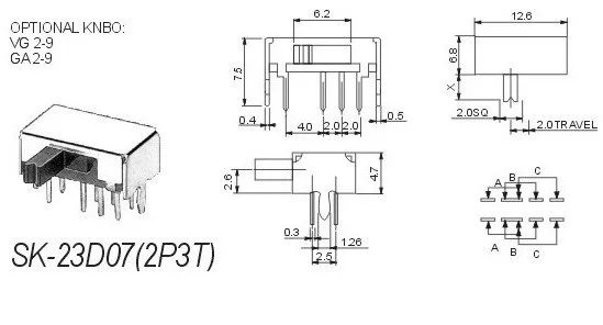
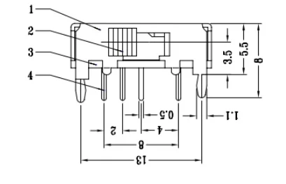
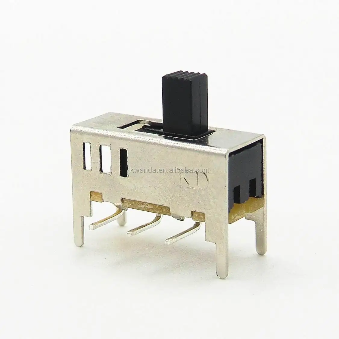
3 pin slide switch wiring. When the switch is closed the pin is tied directly to gnd. A wiring diagram is a simplified traditional photographic depiction of an electric circuit. How to connect a slide switch to an led duration. Slide switches might be for you. Pin 1 is where the rocker switch receives the input power. How to wire an led toggle switch on off 3 prong rocker switch 2020 duration.
These switches are sold in packs of 3. This translates into the following model in a real life rocker switch. It reveals the parts of the circuit as streamlined shapes as well as the power and signal connections in between the gadgets. The wiring diagram to the right will show how to wire and power this 12v 20amp on off on 3 way carling contura rocker switch. Open the code file. They can also be used as a convenient way to choose between two analog or digital input signals.
The resistor in that circuit is a pull up resistor required to bias the input high and prevent a short to ground when the switch is closed. Push the handle of the slide switch to the pin connected with pin 12 which is high level we can light up the led at pin 6 by programming. United states restricted mode. Or these terminals can be ignored for non backlit switch banks. These small single pole double throw spdt slide switches are rated for 300 ma at 50 vdc and make great onoff power switches for low power electronics. Below is a pictorial representation of the schematic diagram.
When wiring this switch you can choose if youd like to illuminate it because of the independent lamp attached to terminals 8 and 7. Wiring products 814104 views. Pin 3 is where the switch is either connected to ground or left open. Need a really basic no frills onoff or selector switch. We have more then 20 years in micro switch on off manufacturingand have got 2 invention patents and 47 utility model patents. The three pins have a 01 spacing that works with standard solderless breadboards.
Select correct board and port. Connect an led to pin 6. Pin 2 is where the accessory that the switch is going to turn on is connected.
Gallery of 3 Pin Slide Switch Wiring

