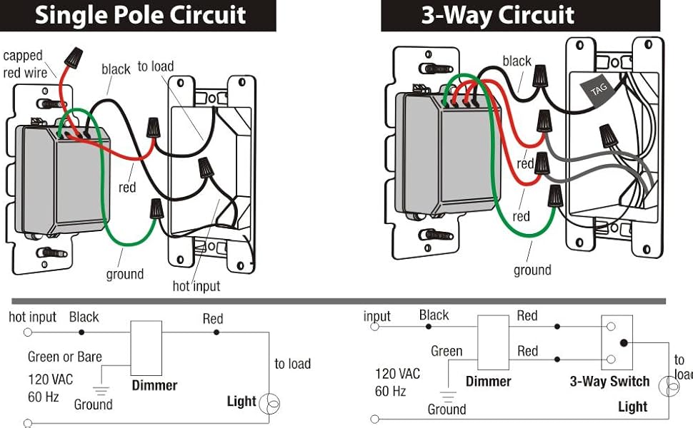
In fact a dimmer can be used this way in place of any of the 3. 4 way switch wring diagram.

3 Way 4 Way Switch
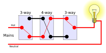
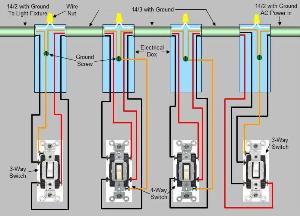
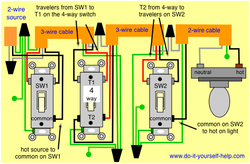
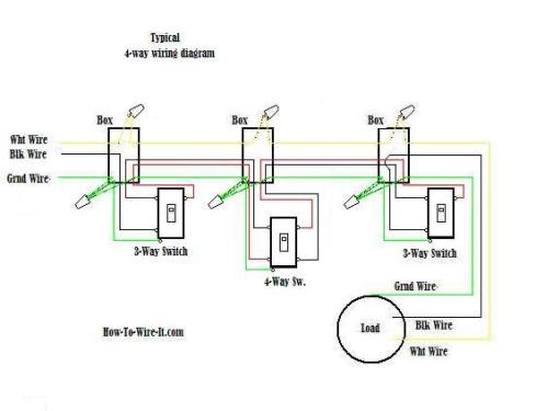
4 way switch diagram. They all must be between the two 3 way switches. Sometimes there is only a switch wiring diagram printed on the inside of the 4 way switch package box. Watch the 4 way switch video below and pay attention. 4 way switch wiring 4 way switch wiring fully explained 4 way switch diagrams. Three wire cable runs between all the switches and 2 wire cable runs to the light. When wiring in the 4 way switch it is most simply described as simply cutting the two traveler wires the two wires that go between the two 3 way switches and terminate on each switch and putting two wires from one switch on the.
The electrical wiring adds additional wiring to the same. This might seem intimidating but it does not have to be. In general practice the diagram above is most often used and is a good guide for wiring a new 4 way switch circuit. When the switch is operated current will either travel straight through or crisscross. It is important to understand how these switches are wired before attempting to troubleshoot or replace. With 4 way switches you must read the manufacturers instructions or wiring diagram.
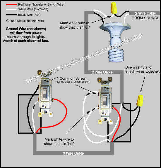
Four way switch wiring instructions inside the switch packaging. Pick the diagram that is most like the scenario you are in and see if you can wire your switch. The white wire becomes the energized switch leg as indicated by using black or red electrical tape. With these diagrams below it will take the guess work out of wiring. Study the 4 way switch and the manufacturers directions. A 4 way switch has 4 terminals or poles.
Two terminalpoles are labeled in and two are labeled out pairs of wires called travelers will connect to each side. A 4 way switch is always placed in between two 3 way switches. Use this if you began repairing and replacing a 4 way switch circuit and ran into problems. 4 way dimmer switch wiring diagram. Take a closer look at a 3 way switch wiring diagram. 3 way switch wiring diagram.
Start here for practical circuits with different arrangments of switches and lights including proper color codes. Back to 3 way and 4 way light switches. Fully explained 3 way dimmer switch wiring diagram will take the mystery out of wiring a 3 way dimmer switch. The wiring connections on 4 way switches varies between manufacturers. To make this circuit work a 3 way dimmer can be used in place of one or both of the standard 3 way switches. The white wire of the cable going to the switch is attached to the black line in the fixture box using a wirenut.
A similar page for 3 way switch circuits. This is the wiring for a dimmer in a 4 way circuit. 4 way switches are a convenient way to operate lighting fixtures from three or more locations. You can have an indefinite number of 4 way switches in a circuit. 4 way switch configurations are used to control lights with three or more switchesa 3 way switch is used on each end with one or more 4 way switches in between the two 3 way switchesthey do not have an onoff position like single pole switches. If you understand how to wire a 3 way switch youll have no issues with a 4 way switch.
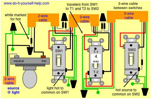
This 4 way switch diagram 2 shows the power source starting at the fixture. My 4 way switches dont work. My 3 way switches dont work.
