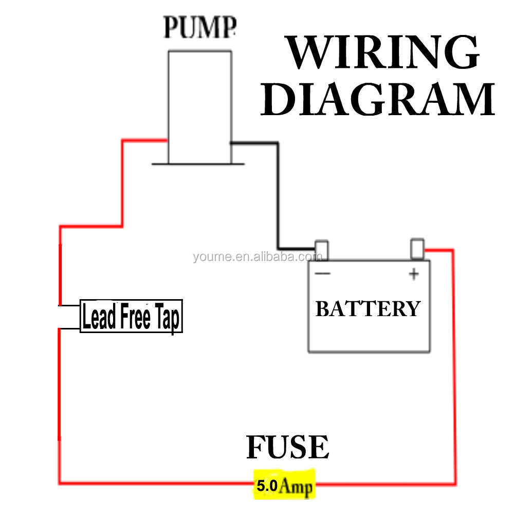
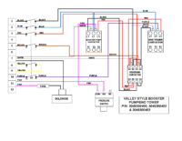
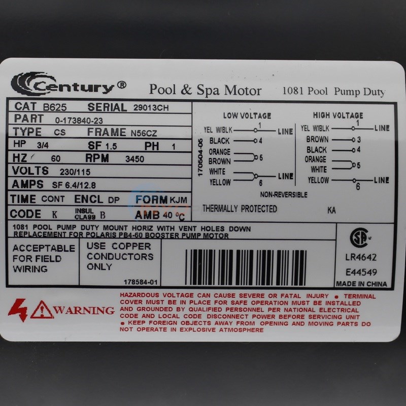
This is how to wire the pb4 60 polaris booster pump and how to read electrical diagram on polaris booster pump change from 120v to 220v skip navigation sign in. Shallow well jet pump system booster installation diagram.

Power 120v Pump From A 240v Circuit Electrical Diy
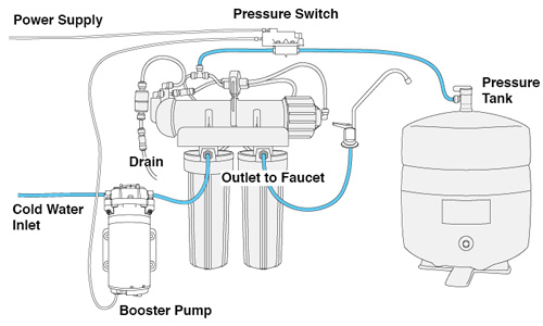
Booster pump electrical diagram. If you have really low water pressure coming from the city supply or have low pressure because you are on a well installing a pressure booster pump could be the solution you have been looking for. Ground polaris pb installation and operation manual. A pressure booster pump can be used to increase the pressure of the water coming into the house. The pump motor must be securely and adequately grounded using the green screw provided. Designing electrical systems for fire pumps since fire pumps are considered life safety equipment they must be reliable. Booster pumps for pool cleaners or solar systems can be operated with 110v or 220v and are usually connected to a separate timeclock powered with a dedicated 15 or 20 amp breaker.
Booster pumps usually come wired for high voltage and looking at the wiring schematics can be intimidating. When designing or installing electrical power supplies for fire pumps and their accessories you must apply special rules as listed in nfpa 70 the national electrical code nec and the standard for centrifugal fire pumps cfp nfpa 20. Single phase wiring diagrams single phase wiring diagram for 05hp pumps with governor switch single phase wiring diagram with governor switch single phase wiring diagram without governor switch three phase wiring diagrams three phase 208v wiring diagram three phase 230v wiring diagram three phase 460v wiring diagram three phase 575v wiring diagram kb pump wiring diagrams kb pump 230v wiring. Submersible well pump accessories installation diagram. These special rules protect the pump. 220v is slightly more efficient and a better choice for either.
The wiring of the motor is identical to the wiring for the main pool pump. Wiring a booster pump. The polaris booster pump supplies high pressure water to the booster pump motor is factory wired for cleaner refer to the typical installation diagram. Operation of pump in this range may result in reduced pump life andor motor damage. If pb0508a031 pump is connected to supply line of sufficient capacity carrying water at 40 psi and the output of the pump is held to 73 gpm by a gate valve the pump will add 40 psi to line pressure for a total output pressure of 80 psi. For the correct voltage.
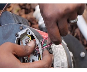
Failure to install in compliance with local and national codes and manufacturers recommendations may result in electrical shock fire hazard unsatisfactory performance and equipment failure. Here is a quick breakdown on swapping from high voltage to low voltage on a 34 hp.


