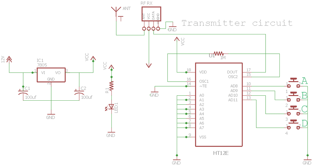
For debugging we will split the circuit into different sections. The above remote control circuit consists of three important components keypad encoder ic ht12e and a rf transmitter rf433 module.
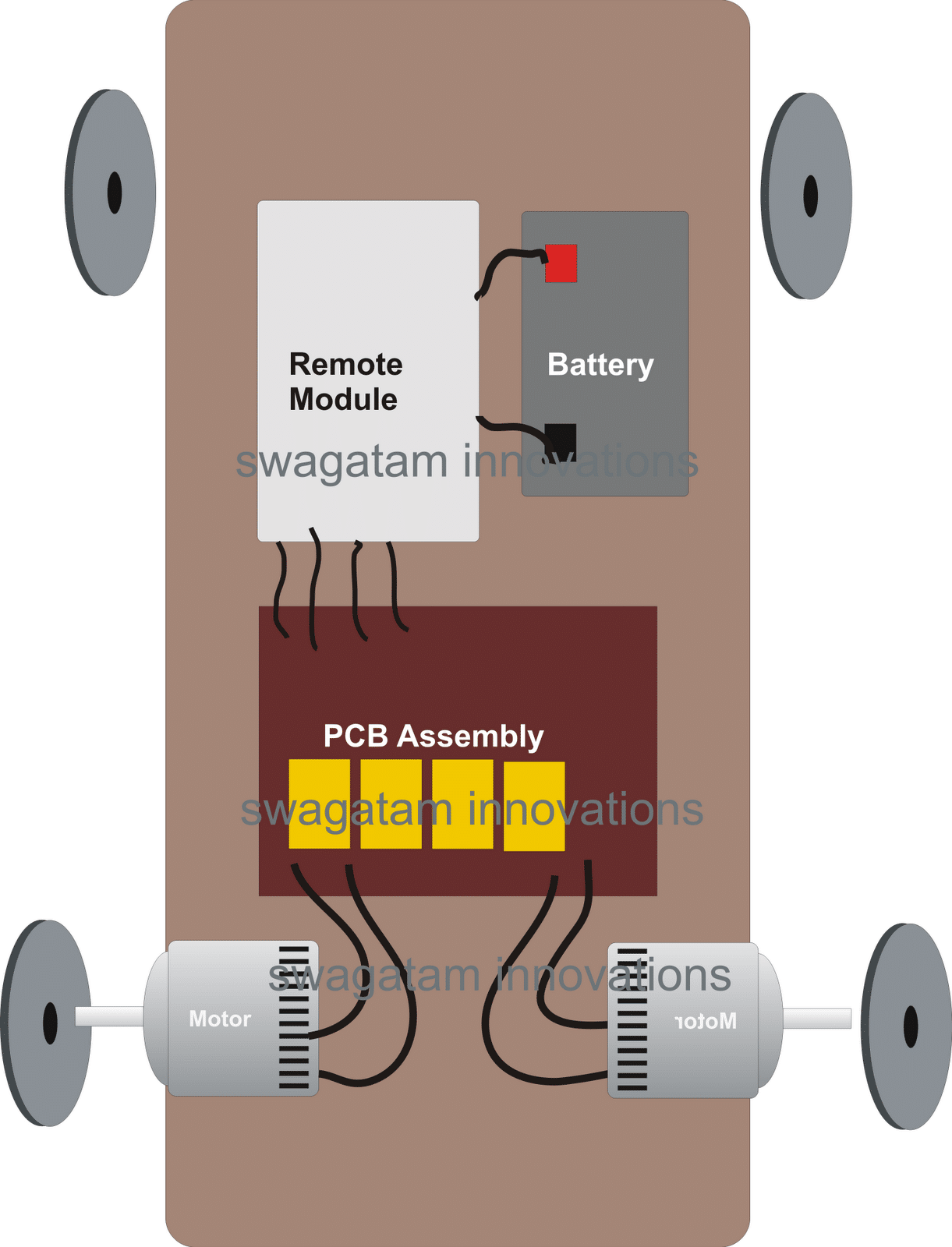
Remote Controlled Toy Car Using 433 Mhz Remote Modules
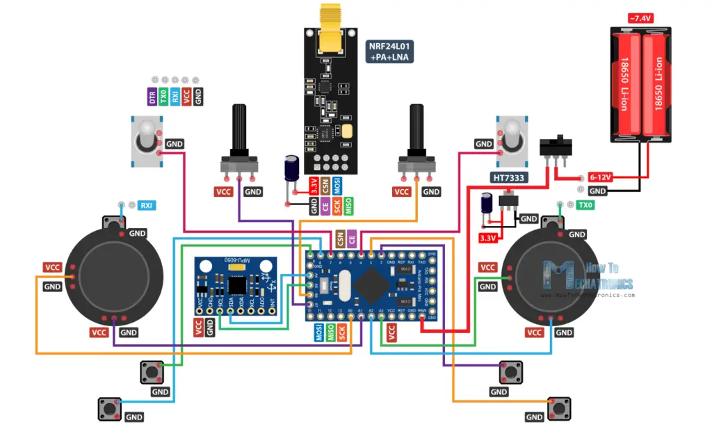
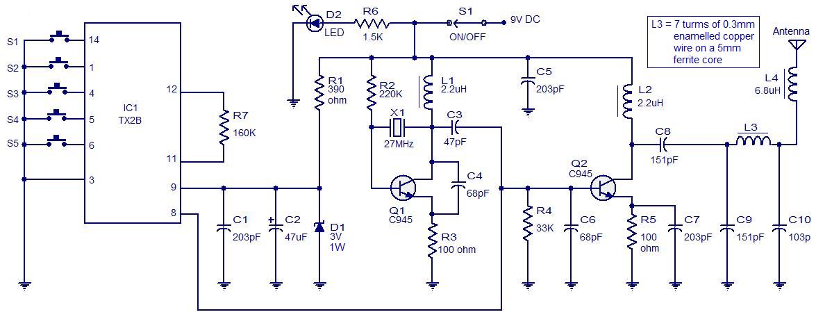
Circuit diagram of remote control car. Et discover 100838 views. When these buttons are pressed it passes the movement signals to the encoder. Remote uses four button switches s1 s2 s3 and s4 to control the toy. We have used ic 4017 to convert it into a push on push off switch. Remote control circuit through radio frequency without microcontroller description this is a simple type remote control by using rf communication without microcontroller. In the transmitter circuit you will find two astable multivibrators.
Give vcc5v and gnd to the ic and then give the 12v to pin 8. Circuit diagram for bluetooth controlled car is shown in above figure. The keypad for our remote is made up of four individual buttons which is wired to the data pins of the data pins ad0 to ad3 of the encoder ic. Receiver circuit is connected to ac appliance via relay so that we can control the light remotely. And by touching stop button we can stop the car. Circuit diagram and explanation.
This remote controlled toy car circuit consisting of an infrared transmitter receiver pair uses ir beam transmission to switch the toy car on or off. A motor driver is connected to arduino to run the car. To operate the toy car you need to hold the transmitter in your hand keeping it pointed at the toy car which has the receiver fitted inside and simply press a switch provided on. Free pcb files and circuit diagram. Digital datas from the switches are encoded by the ht12e encoder ic and are transmitted to the receiver through ask rf module. Connect the enable pins of the motors to 5v.
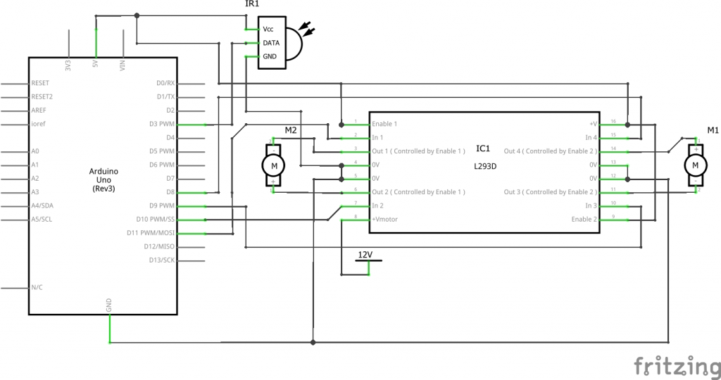
4 channel rf transmitter receiver with motor controller for rc car. In this section i will discuss how to debug the remote control circuit. How to make ir 4 channel remote control system. Motor drivers input pins 2 7 10 and 15 are connected to arduinos digital pin number 12 11 10 and 9 respectively. You can use any remote of tv ac dvd player to control the movement of motors. Rc car circuit diagram with remote transmitter is designed in a compact way to make it as small as possible.
This low cost circuit is based on the cd4017 counter ic which receives trigger pulse from ir sensor and switch on the relay. Remote control toy car circuit can be used to on and off the motor of the toy car with the help of your remote. Remote control transmitter circuit the transmitter circuit is constructed around two bc558 transistors t1 and t2 3 bc548 transistors t3 t4 and t5 ir led1 and a several discrete components. Place the ic on a breadboard. In this project a remote has. In this remote controlled switch circuit we are using tv remote to onoff the ac light by pressing any button of remote and using the tsop1738 at receiver end.
First of all dont be angry and just keep calm.
