When clapped connected load is switch on. You can switch on and switch off the appliance at your room by simple clapping or by a sound.
9 Way Clap Switch Circuit
Clap switch circuit diagram using relay. In the first circuit i will control a single relay using clap switch. High sensitive clap operated switch circuit without microcontroller. Simple clap switch circuit diagram 220v using relay. Today we are going to make a simple clap switch circuitthis is a simple clap switch circuit with high sensitivity. The only unusual component is the single coil latching relay. Again clap load is switch off.
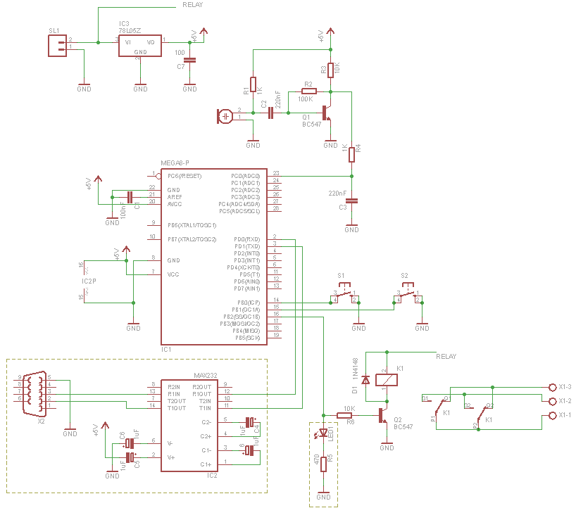
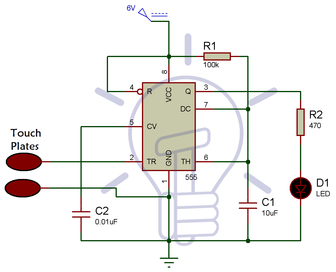
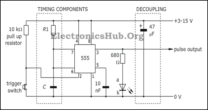
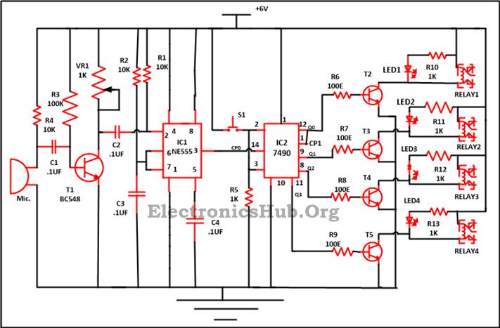
Pin2 vcc 5v pin4 gpio1 programmed as an input pin5 gpio0 programmed as an output pin7 ground the relay switch. A relay is a switching device which is used to switch the circuit on when required and turn off whenever required. While there are numerous means of generating the latching function the latching relay greatly simplifies the circuit and provides a relay contact interface for driving a 115 or 230vac load such as a light bulb. If you want to design a switch circuit to turn on and turn off without reach a physical switch then try this simple clap switch circuit with relay this circuit is designed with timer ic 555 dual d flip flop ic 7474 and a electromagnetic relay. Clap switch circuit using 555 and 4017. When you clap for the second time the relay is deactivated and the light is turned off.
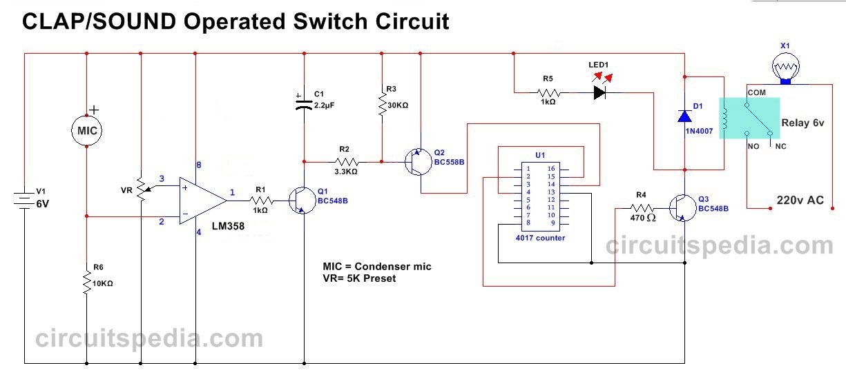
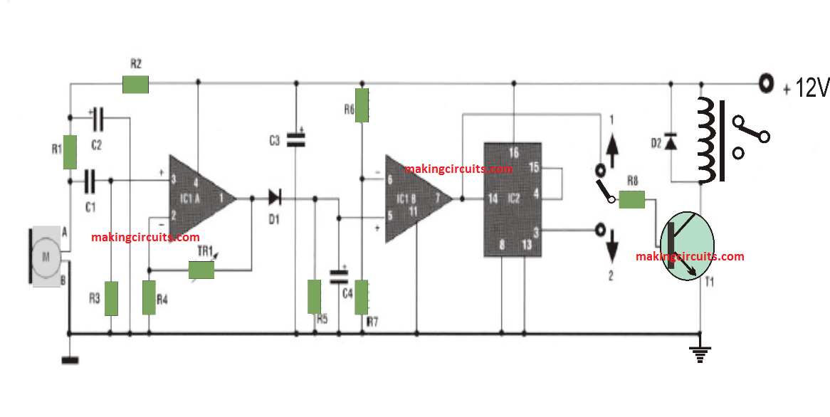
The circuit can sense the sound of claps from a distance of 1 2 meters. Although its name is clap switch but it can be turned on by any sound of approximately same pitch of clap soundthe main component of this clap switch circuit is the electric condenser mic which has been used as a sound sensorcondenser mic basically converts sound energy into electrical energy. Fariha zahid 5 days ago. Clap switch with relay by circuit diagram if you want to design a switch circuit to turn on and turn off without reach a physical switch then try this simple clap switch circuit with relay this circuit is designed with timer ic 555 dual d flip flop ic 7474 and a electromagnetic relay. Resistors 100 ω r1 560 ω r2 46 kω r3 18 kω 3 r4 33 kω r5. Clap switch is an interesting hobby circuit which turns on the lights with a clap sound.
When you clap once the relay is activated and the light or any load is turned on. This is a simple clap switch circuit with high sensitivity. A resistor is an electronic component which opposes the flow of current or prevents excess leakage of current in the circuit when required. The diode does nothing to drive the relay but it. In order to drive our 5v relay using the output of a pic we have to set up a driver circuit which in this case is a simple npn transistor and a diode. Sound controlled toggle switch using cd4017 decade counter ic.
It switches onoff electrical appliances through clapsin the circuit i will control a single relay using clap switch. Sensitive clap switch circuit using cd4017 decade counter. Condenser mic is worked as sound sensor.
Gallery of Clap Switch Circuit Diagram Using Relay