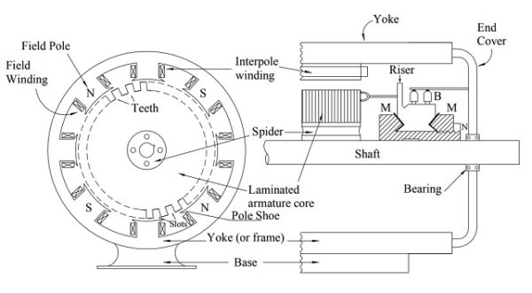
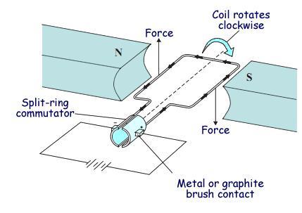
The components of this motor mainly include the rotor the armature commutator stator axle field windings and brushesthe fixed component of the motor is the stator and it is built with two otherwise more electromagnet pole parts. In an electric motor the operation is dependent upon simple electromagnetism.
Brushed Dc Motor Control Mosfet Selection Electrical
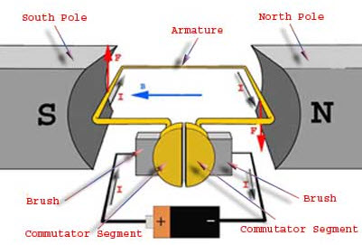
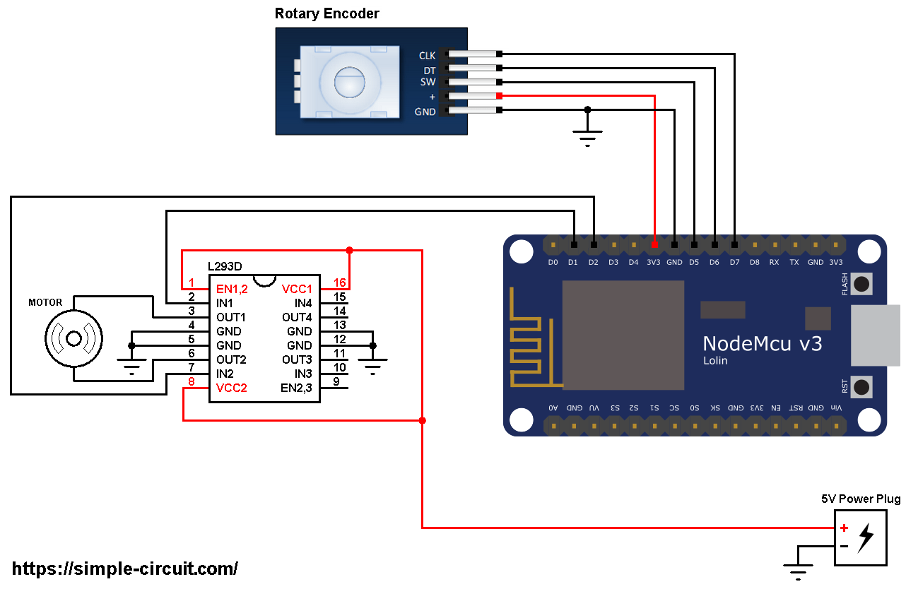
Dc motor diagram. The armature contains an electromagnetwhen you run electricity into this electromagnet it creates a. The above diagram shows how to connect the l298 ic to control two motors. There is no basic difference in the construction of a dc generator and a dc motor. Following is the schematic diagram of the dc motor interface to arduino uno board. The circuit diagram of the proposed dc motor speed controller can be seen below. The dc motor is the simplest of the motors discussed here.
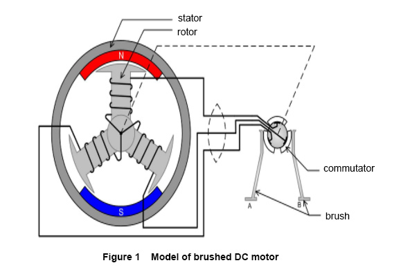
As you may witness although the bulb works perfectly in response to the pwms and varies its intensity from minimum glow to. In a typical dc motor there are permanent magnets on the outside and a spinning armature on the inside. A dc motor is an electric motor that runs on direct current power. The dc motor was the mainstay of electric traction drives on both electric and diesel electric locomotives street carstrams and diesel electric drilling rigs for many years. There are two terminals and when you apply direct current to one terminal and ground the other the motor spins in one direction. The construction of the dc motor and generator are same.
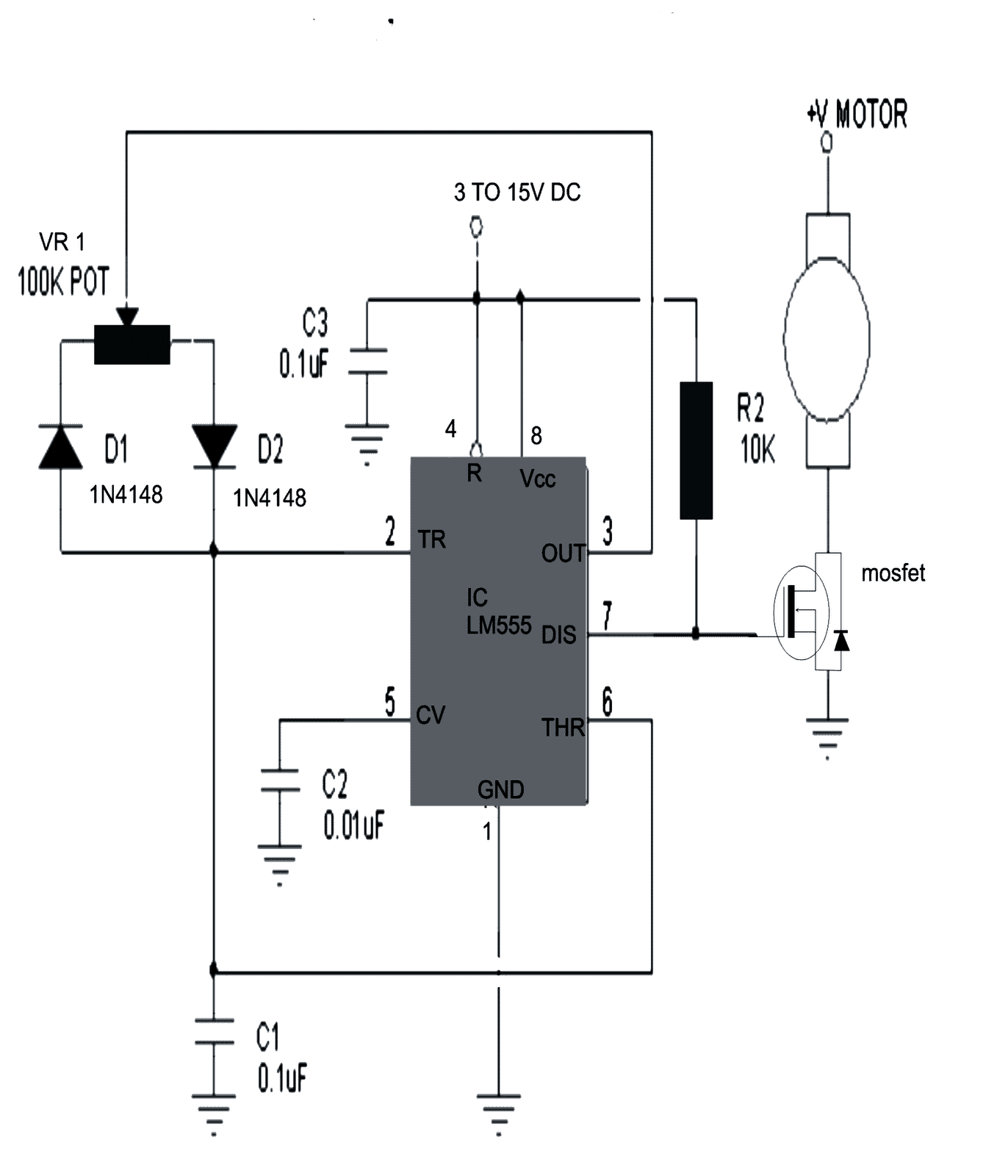
Dc series motor components used in dc series motor. The article how electric motors work explains how brushed motors work. Figure 4 shows a photo of a small dc motor. Dc motors are seldom used in ordinary applications because all electric supply. But the dc motor has the wide range of speed and good speed regulation which in electric tractionthe working principle of the dc motor is based on the principle that the current carrying conductor is. In the above video clip we can see how the ic 555 based design is used for controlling speed of a dc motor.
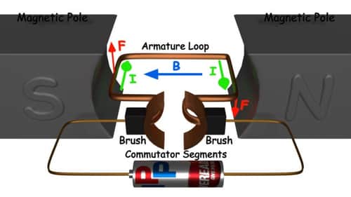
The dc motor converts the electrical power into mechanical power is known as dc motor. There are three input pins for each motor input1 in1 input2 in2 and enable1 en1 for motor1 and input3 input4 and enable2 for motor2. Like generators there are different types of dc motors which are also classified into shunt wound series wound and compound wound dc motors. A current carrying conductor generates a magnetic field when this is then placed in an external magnetic field it will encounter a force proportional to the current in the conductor and to the strength of the external magnetic field. It works on exactly the principle discussed above. The introduction of dc motors and an electrical grid system to run machinery starting in the 1870s started a new second industrial revolution.
A brushed dc electric motor is an internally commutated electric motor designed to be run from a direct current power source. Brushed motors were the first commercially important application of electric power to driving mechanical energy and dc distribution systems were used for more than 100 years to operate motors in commercial and industrial buildings. The permanent magnets are stationary so they are called the statorthe armature rotates so it is called the rotor. In fact the same dc machine can be used interchangeably as a generator or as a motor.
Gallery of Dc Motor Diagram