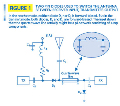
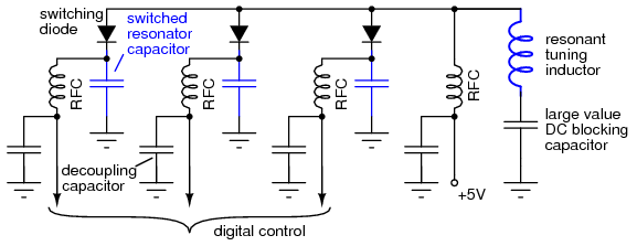
It has low ideally zero resistance in one direction and high ideally infinite resistance in the other. The pin diode switch can be used for antennas with impedances of from 50 ω up to 75 ω.
Lessons In Electric Circuits Volume Iii Semiconductors
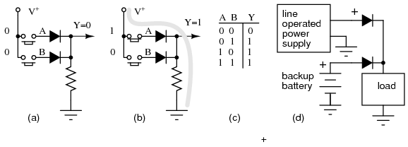
Diode as a switch circuit diagram. In the above figure the switches s 1 and s 2 are the self commutating switches. A diode vacuum tube or thermionic diode is a vacuum tube with two electrodes a heated cathode and a plate in which electrons can flow in only one direction from. The output across the diode will be constant. Diode vehicle security system applications. The basic diagram of zener diode as voltage regulator is given below. A simple block diagram of a guitar with a distortion circuit looks like this below.
The first shows the anode tied to ground through r1 and the cathode tied to the vcc power rail. Rf switch with pin diodes circuit diagram. Circuit diagram of overvoltage protection using zener diode. A diode is a two terminal electronic component that conducts current primarily in one direction asymmetric conductance. Distortion pedals are made using a minimum of the two most important things namely the preamplifier section and the diode clipping circuit. The signal to noise ration of the receiver deteriorates somewhat up to 1 db.
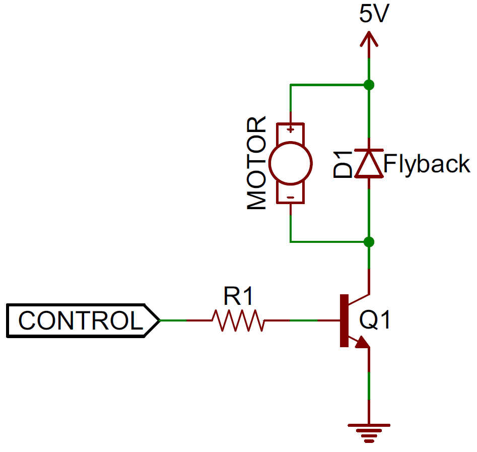
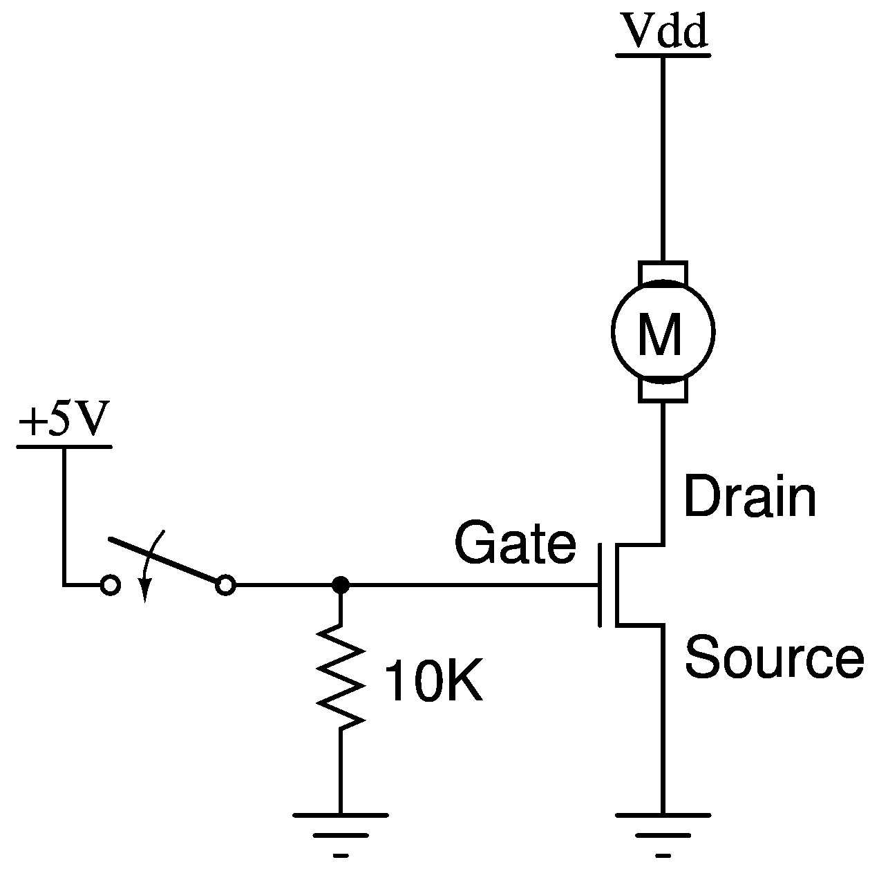
The operated diodes block the disconnected antennas by about 30 db. The following diagram illustrates how a diode can be added to a factory circuit to isolate the alarm or other device so that when activated it will power just one of the components in a circuit instead of all the components in the circuit. To illustrate a basic diode switch weve prepared a couple of simplified circuit diagrams. The following circuit explains the diode acting as a switch. Simple touch sensitive switch circuit using 555 timer bc547 transistor. Where each switch is connected to diodes d 1 and d 2 parallelly.
The above circuit symbolizes that the diode gets on when positive voltage forward biases the diode and it gets off when negative voltage reverse biases the diode. First we consider the working of the circuit when the power supply is working properly. The zener diode can work as a voltage regulator if it is introduced in a circuit. As we know if the voltage across the diode exceeds a certain value it would draw excessive current from the supply. A switching diode has a pn junction in which p region is lightly doped and n region is heavily doped. Where rl is the resistive load v s 2 is the voltage source s 1 and s 2 are the two switches i 0 is the current.
The circuit diagram for the overvoltage protection circuit is given below. Ldr circuit diagram ldr sensor circuit darkness circuit using comparator lm358. The switch s 1 will conduct when the voltage is positive and current is negative switch s 2 will conduct when. Generally a distortion pedal circuit is used in between the guitar audio source and the power amplifier. Signal losses at the closed diode is negligible. It is driven by a current source.
Gallery of Diode As A Switch Circuit Diagram