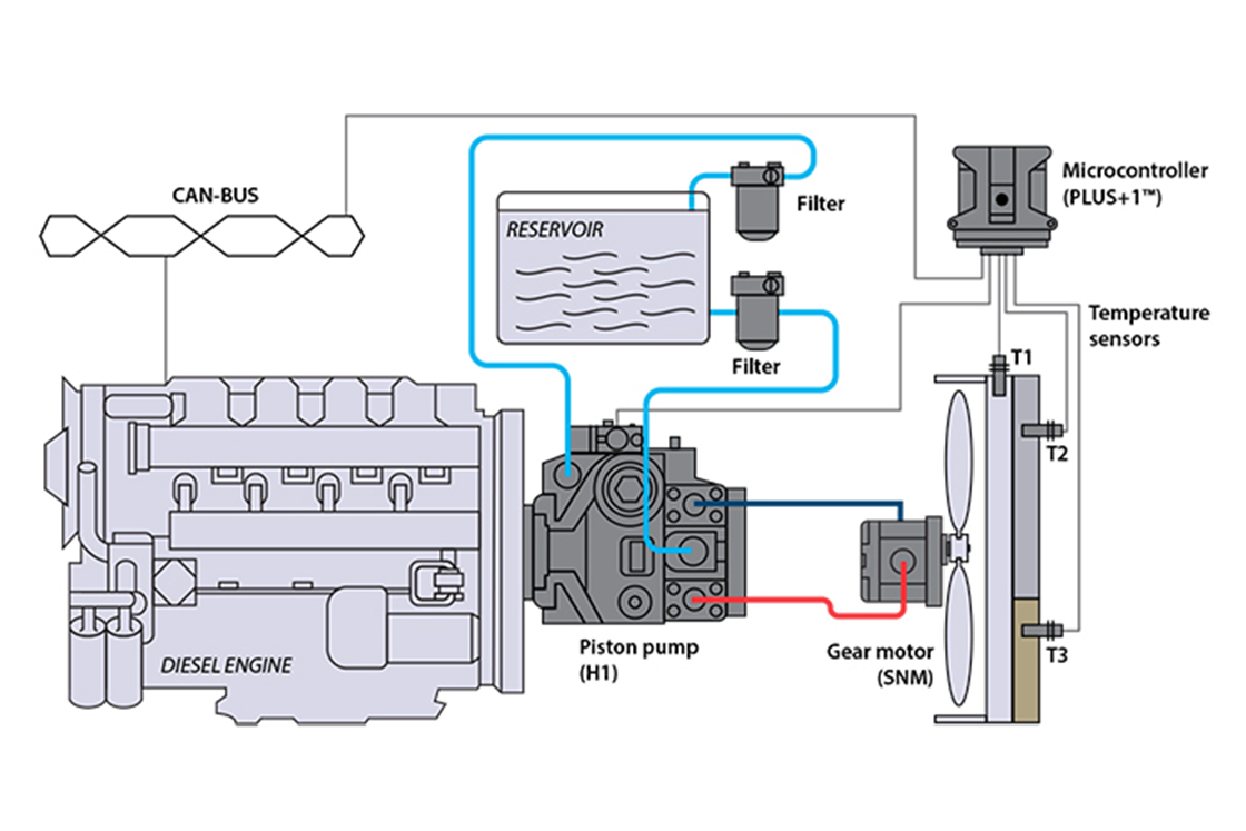
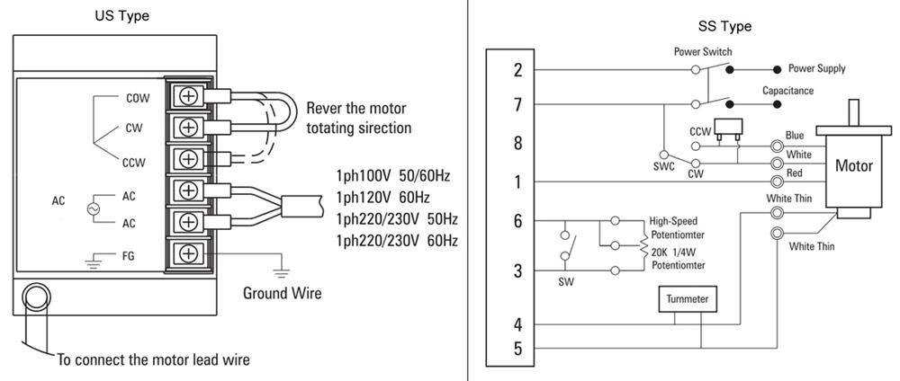
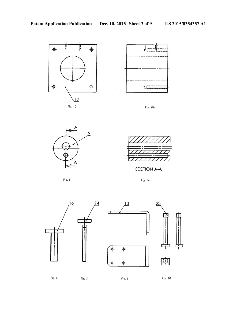
Reversing the direction of flow can reverse the direction of rotationas in the case of gear pumps volumetric displacement is fixed. When pressure fluid is.
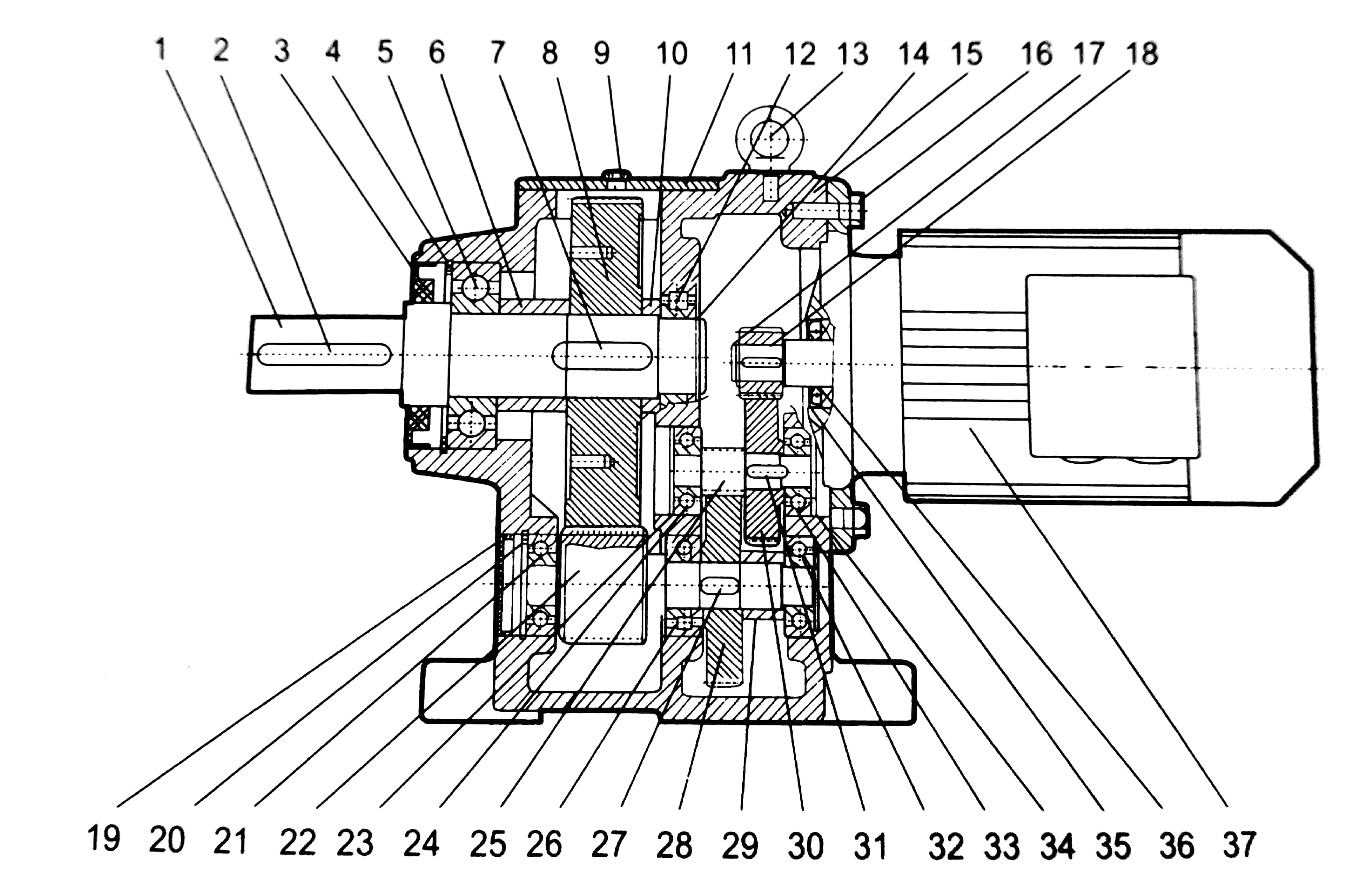
Inline Helical Gearbox Helical Gear Motor Geared Motor
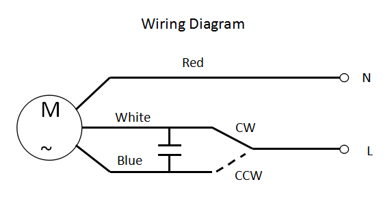
Gear motor diagram. Unused text does not appear but remains available if you switch layouts. It is easy and free. Most of the gear motors are bidirectional. Gear motor wiring diagram new ac gear motor wiring diagram bodine bodine electric motor wiring diagram download what is a wiring diagram. Free download gear diagram software and view all examples. Connection diagram for 230460vac 9 wire reversible 3 phase gearmotors and motors 07410012.
Parallel shaft singlethree phase. It demonstrates how the electric cables are adjoined and also can additionally show where. Parallel shaft wash down duty singlethree phase. Bodine electric company is a leading manufacturer of fractional horsepower gearmotors motors parallel shaft gearmotors and motor speed controls. The teeth are shaped so all of the teeth of the inner gear are in contact with some portion of the outer gear at all times. A direct drive gerotor motor consists of an inner outer gear set and an output shaft fig.
Bodine electric offers over 1300 standard products and thousands of custom designed gearmotors motors and speed controls. Complete exploded views of all the major manufacturers. Parallel shaft 230v three phase parallel shaft 115230v 100 175 series. Sew eurodrive is a leading company in the field of drive engineering. Internal gear motors fall into two categories. Due to the high pressure at the inlet and low pressure at the outlet a large side load on the shaft and bearings is produced.
Parker is a global manufacturer of hydraulic pumps transmissions gear pumps and motors engineering superior products for a wide variety of applications. The inner gear has one fewer tooth than the outer. Parallel shaft 482 series. Delivering unsurpassed quality and performance parkers extensive line of hydraulic pumps and motors helps you select the right product for your hydraulic application. A wiring diagram is a basic graph of the physical connections and physical layout of an electric system or circuit. The range of products offered includes gearmotors frequency inverters and drive solutions from one source.
Gear diagram is used to show interlocking ideas each of the first three lines of level 1 text corresponds to a gear shape and their corresponding level 2 text appears in rectangles next to the gear shape. Right angle gear motor. Parallel shaft gearmotors 3 phase inverter duty. Hydro gear hgm 15e 3138 exploded view parts lookup by model. Small ac gear motors pellet corn stove gear motors. To verify that this is the correct wiring diagram for your bodine product please check for the connection diagram reference number in the specifications table on the applicable itemmodel page.
Click download pdf to view this wiring diagram.


