The circuit shown here provides two direction control forward and reverse for a three phase electric motor. Plc example for motor.

Motor Control Circuit Wiring Instrumentation Tools
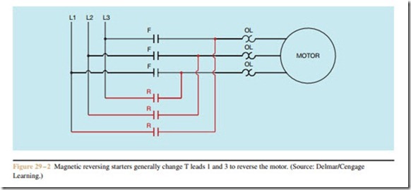
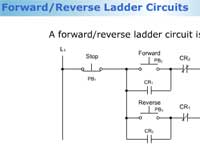
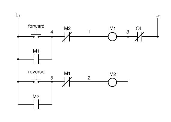
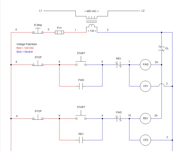
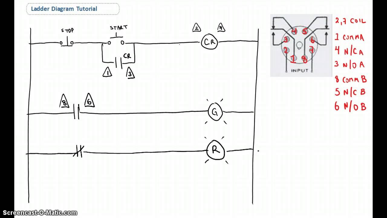
Ladder diagram of forward reverse motor control. There are lots of motors and conveyors used in industries for different purposes. If we wanted to keep the motor running even after the operator takes his or her hand off the control switches we could change the circuit in a couple of different ways. In this wiring diagram both the forward and reverse coils have their returns connected to l2 and not to the overload contacts. To keep the motor running even after the operator removed its control switch s we could change the circuit in several different ways. The interlock contacts installed in the previous sections motor control circuit work fine but the motor will run only as long as each push button switch is held down. For the love of physics walter lewin may 16 2011 duration.
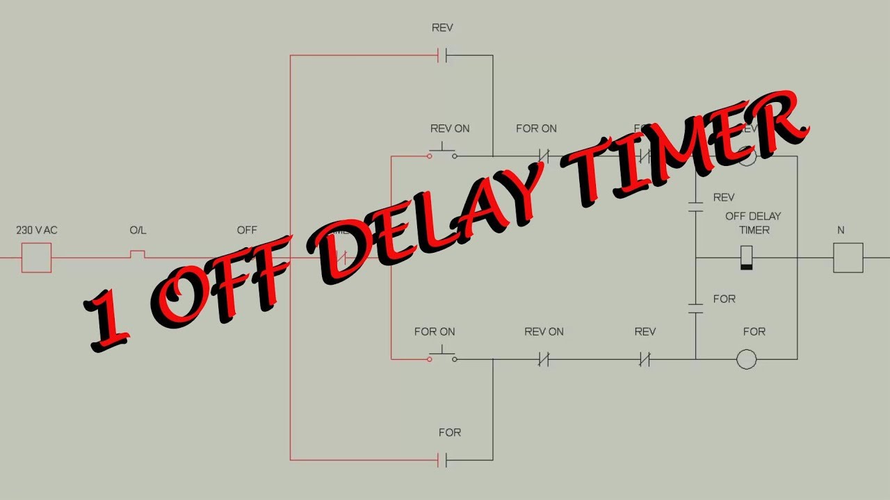
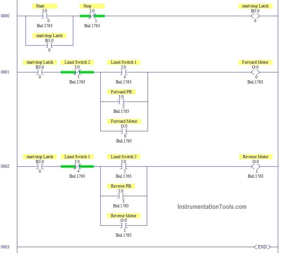
The workpiece starts moving on the left side and moves to the right when the start button is pressed. In this convention the hot. Motor forward and reverse direction control using plc duration. We could replace the push button switches with. Electrical wiring diagram forward reverse motor control and power circuit using mitsubishi plc this blog post is not only intended to provide a graphical illustration but will also explain the procedure and the operational concept involving the wiring principle of the forward reverse motor control circuit with the use of a plc programmable. We could replace the pushbutton switches with toggle switches or we could add more logic of relay.
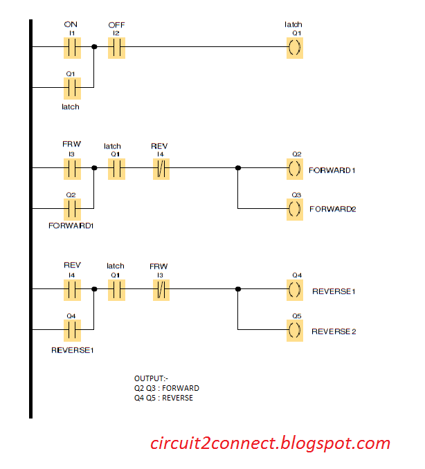
The overload contacts are connected to l1 on one side and to the plcs input module on the other input 003. Figure 5 forwardreverse motor wiring diagram. Motor reverse and forward ladder logic programming. Solve the virtual lab at nitk 13844 views. Make the example ladder logic to control the motor in forward and reverse direction using plc programming with limit switches as sensors. Interpret this ac motor control circuit diagram explaining the meaning of each symbol.
I hope the above forward reverse motor control diagram 3 phase motor forward reverse starter wiring diagram help you to understand this connection. In some cases motors or conveyors need forward and reverse operation for some control purpose. An alternative to the conventional schematic diagram in ac power control systems is the ladder diagram. 3 phase motor control using plc. I hope you will share this post on social media. Now if you have any question and have any suggestion then you can use the below comments box.
There are two motor m1 and m2 one allows forward rotation and the other one allows reverse rotation. Lectures by walter lewin. Ladder logic program for motor control is explained below. This is plc program for forward and reverse control for 3 phase asynchronous motor. In the event of an overload both motor starter output.
Gallery of Ladder Diagram Of Forward Reverse Motor Control