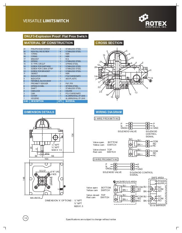
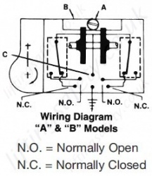
The structure of a typical vertical limit switch is shown in the following figure as an example. Limit switch styles.
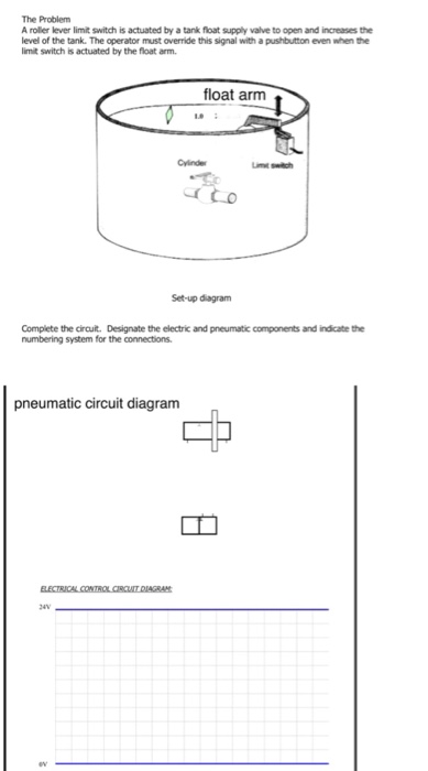
Solved A Roller Lever Limit Switch Is Actuated By A Tank
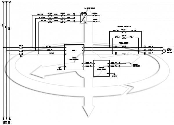
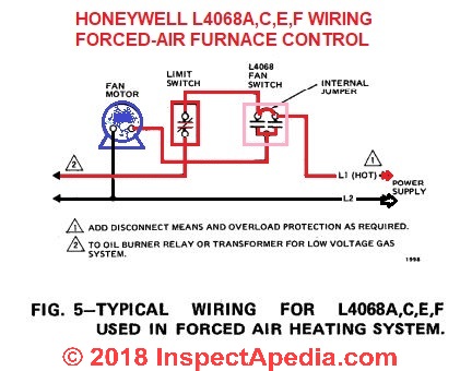
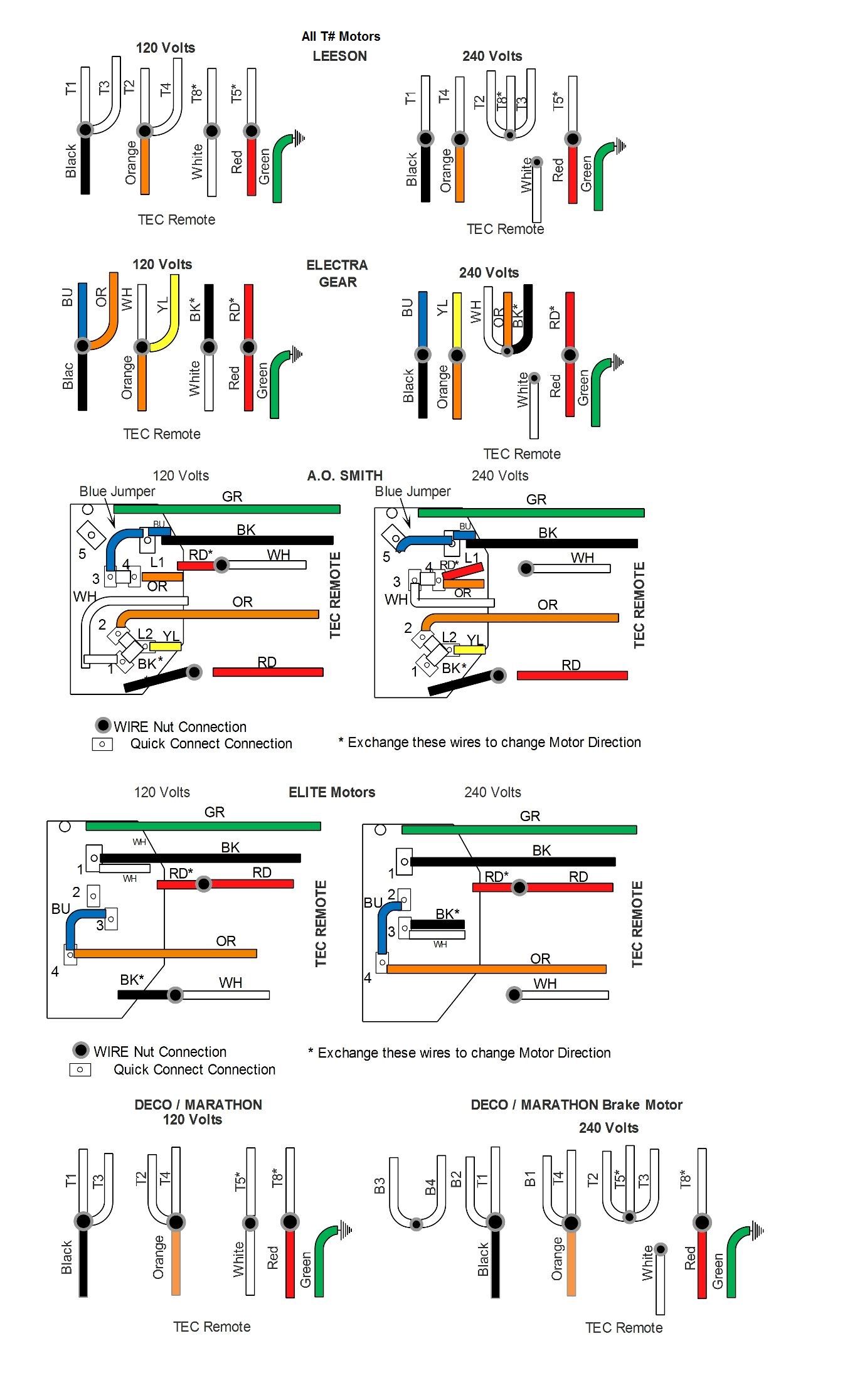
Limit switch connection diagram. Explanation of wiring diagram 1. 3 way switch wiring diagram. How to form pour and stamp a concrete patio slab duration. With these diagrams below it will take the guess work out of wiring. The switch body can be quickly and easily replaced in the field without having to rewire the connections to the terminals in the receptacle. It has three terminals.
The black wire power out wiring attaches to the other switch screw. The power input terminal is called the common terminal and is used to connect the switch to a power source. The screw terminals on the switch body provide connection points with the nc and no contacts inside the switch. Pick the diagram that is most like the scenario you are in and see if you can wire your switch. The shapes of limit switches are broadly classified into horiz ontal vertical and multiple limit switches. Rated impulse dielectric strength uimp the peak impulse voltage that the switch can withstand with no insulation breakage.
The majority of new industrial applications today utilize the plug in design switch due to its superior sealing and ruggedness. Beginners guide to home and limit switch hardware mach3 cnc duration. If you explain what motor you plan to use and the motors data we can maybe do an actual drawing of what we might suggest. A typical limit switch design uses a lever with a roller tip to make contact with the moving part. Take a closer look at a 3 way switch wiring diagram. Structural diagram of typical vertical limit switch seals actuator head built in.
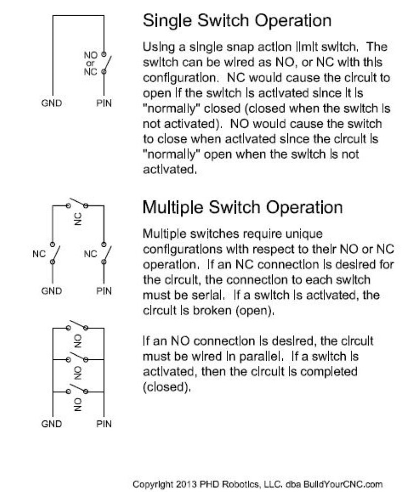
Limit switches are generally composed of five components. Switch wiring shows the power source power in starts at the switch box. Fixture wiring exits the switch box. It is abbreviated com the other terminals are the normally open no. Circuit electrical wiring enters the switch box. Most of the limit switches in this design share a common terminal between the nc and no contacts like this.
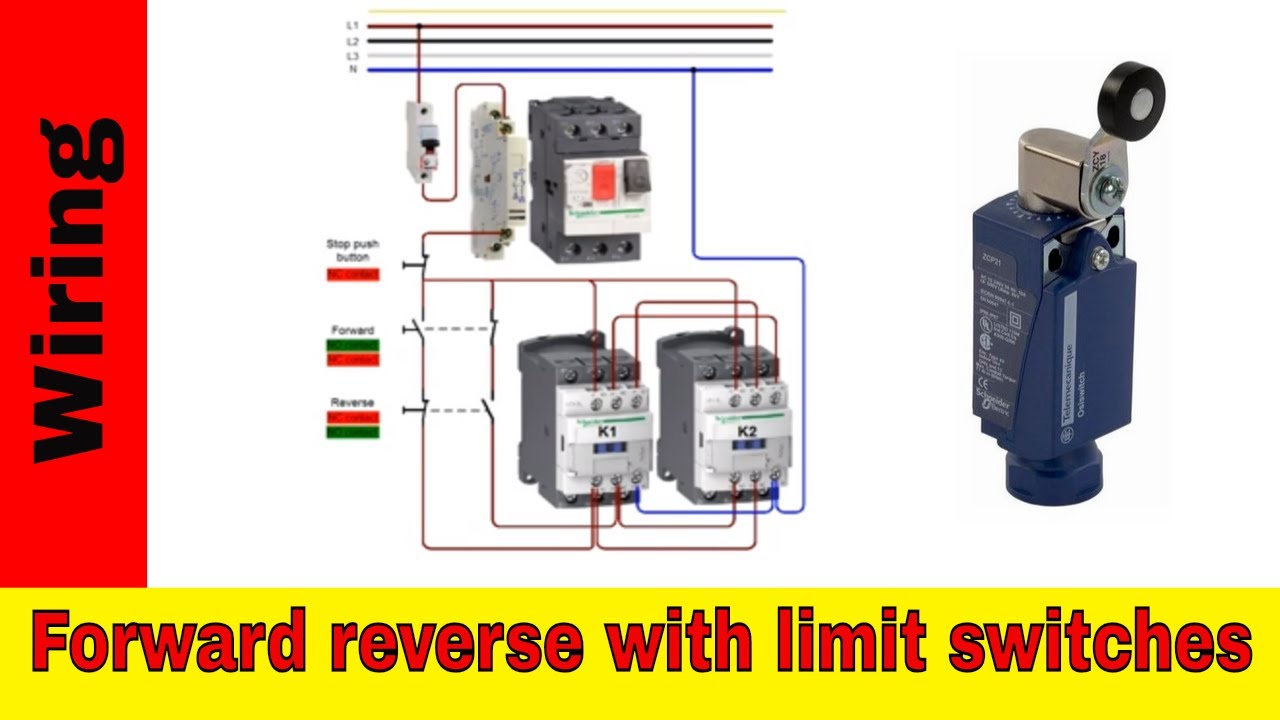
A limit switch is used to control electrical devices by breaking and completing electrical circuits. The rated permissible upper limit temperature is 65c if the terminals are made of brass. Circuits like this are called a latching circuit or a latching motor circuit. The black wire power in source attaches to one of the switch screw terminals. In my simple drawing s1 is a nc normally closed limit top and s2 is a no limit switch. This video will describe about limit switch with detail working principle animation connection and applications of limit switch.
Please subscribe our channel daily electrical to get regular. This might seem intimidating but it does not have to be. Upper limit temperature of the switch if it is a model with its charged part sealed.
Gallery of Limit Switch Connection Diagram