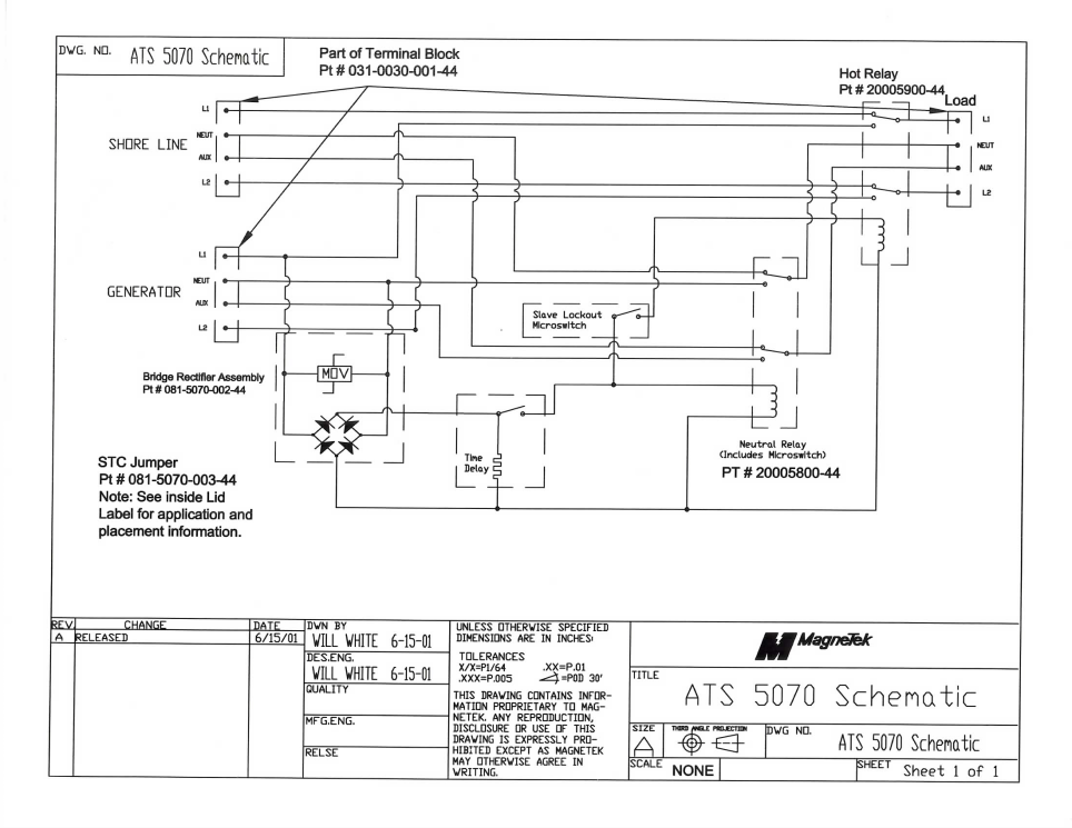
If utility power fails the switch connects. In the above manual changeover switch wiring diagram i shown the incoming supply from the energy meter incoming supply form the portable generator and out going supply to load or house load.
3 Phase Manual Changeover Switch Wiring Diagram For Generator
Manual changeover switch connection diagram. In the diagram i shown handle type manual changeover switch. 1 cm and 5mm thick mdf board 2. 3 phase manual changeover switch wiring diagram or three phase manual transfer switch wiring diagram. The manual changeover switch has 2 lights built into it that indicate the presence of power either from the mains electricity provider or the generator. 63 amp 4 pole changeover switch on load type 3 its lt make model number was not mentioned anywhere 3. In which i done all the connection.
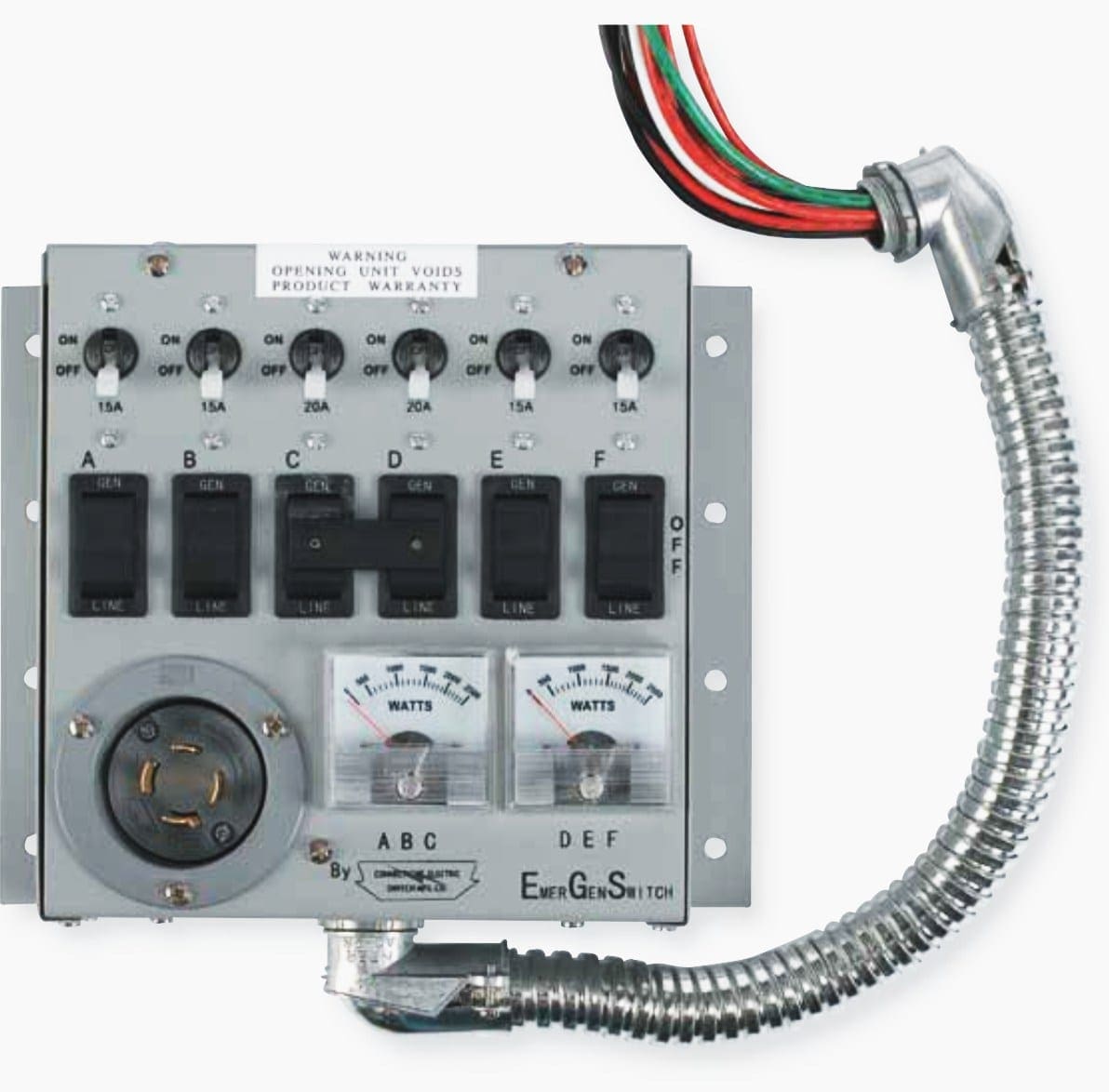
A toggle switch for switching on off the voltmeter 1 5. A buzzer or siren can also be fitted to the manual switch in order to give the user an audio queue once mains electricity is restored. 2turn the motormanual selector to the manualmanposition. In this step by step tutorial we will be showing the portable generator wiring and connection diagram to the home supply and main distribution boardwe will be using automatic changeover switch also known as automatic transfer switch ats manual changeover switch mts or manual transfer switch to connect the generator to a house. This video is about manual changeover switch this video explains how a manual changeover works manual changeover switch connection. A buzzer or siren is an additional extra.
How to do rotary cam changeover switch wiring connection in urdu and hindi. Figure 3 1 operating the switch manually to disable the manual and at the same time also electrical operation turn the handle to the position o and attach the padlock to the. In fig 2 different connection and wiring diagrams are shown for a two pole single phase manual changeover switch. 720 copper wire a few meters 7. In addition we may also wire a portable generator to home. 63 amp rated 3 terminal connectors 2 4.
Phase indicator lamps ryb 3 6. Figure 4 wiring diagram of a manual transfer switch in the off position figure 5 wiring diagram of a manual transfer switch in the on position. The upper portion of the changeover switch is directly connected to the main power supply while the lower first and right connections slots are connected to the backup power supply like generator or inverter. When utility power is functioning the wires from the circuit breaker in the main electrical distribution panel are connected to the generator sub panel. As you know that i already published a post and diagram about the manual changeover switch wiring diagram single phase with complete installation and wiring connection method. 0 230 v digital voltmeter 1 5.
Wiring diagram energy meter. 3attach the handle to the switch panel by pressing it to the changeover switch until is clicks into place. Electric manual changeover switch connection ewc jan 2019. Following materials were used.


