It shows the elements of the circuit as streamlined shapes as well as the power as well as signal connections in between the tools. O the project looks like pcsmotordemo1.
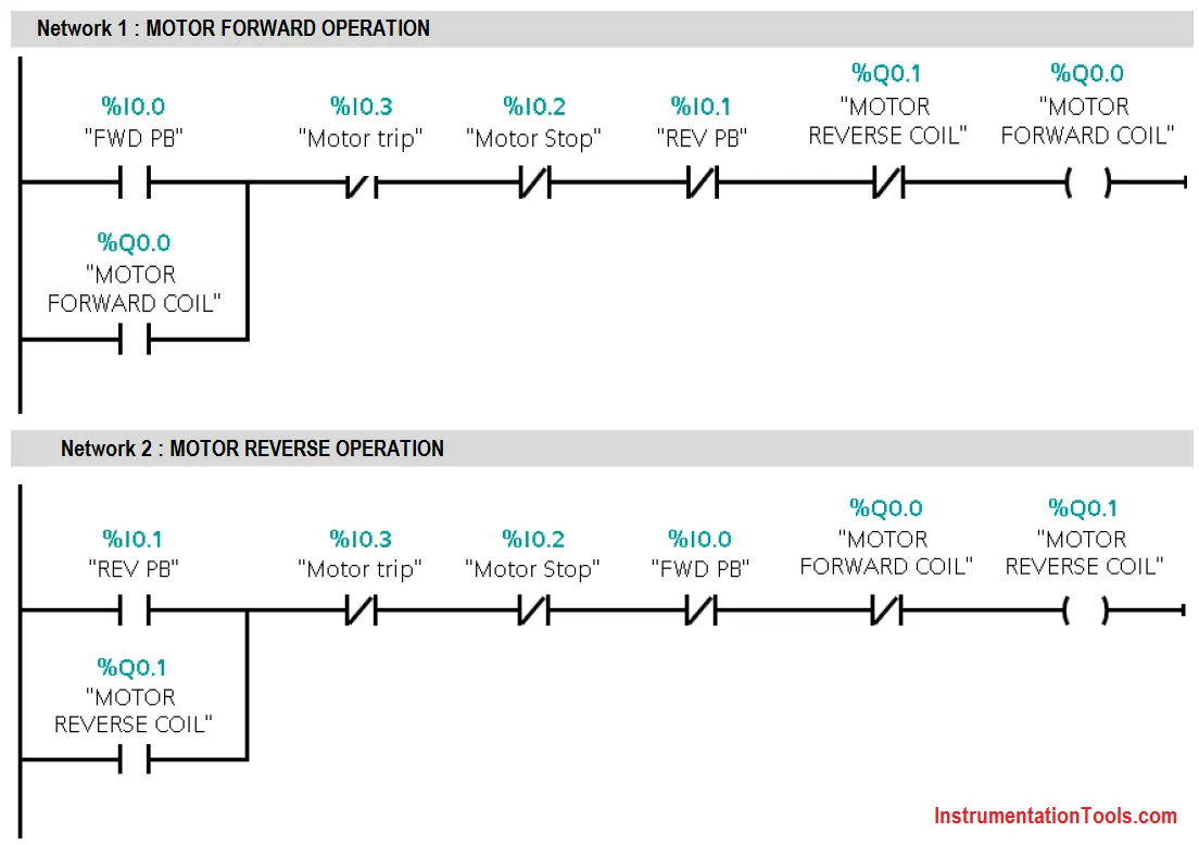
Forward Re Verse Control Developing A Wiring Diagram And
Motor control circuit diagram with plc pdf. Figure 5 below shows a schematic diagram for a plc based motor control system similar to the previous motor control example. Today i will walk you through programming a very basic stop start circuit for an electric motor. How exactly do overload heaters protect an electric motor against burnout from overcurrent. If we wanted to keep the motor running even after the operator takes his or her hand off the control switches we could change the circuit in a couple of different ways. Take this circuit section for example with wire 25 as a single electrically continuous point threading to many different devices. When including a plc in the ladder diagram still remains.
This should help you get a handle on some of the basics. Do so figure 11. In a control circuit possesses the same wire number. But it does tend to become more complex. L2 control circuit where a normally closed switch contact by the same name ol is connected in series with the motor relay coil. However if you take your time and learn the basics it can be an easily achievable task.
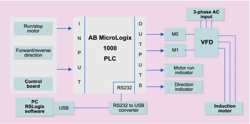
A wiring diagram is a simplified conventional photographic representation of an electric circuit. Special control circuits75 76 multispeed motor connections76 77 1 phase76 3 phase76 77 programmable lighting controllers78 class 886578 ac lighting contactors79 81 class 890379 81 load connections79 control circuit connections80 panelboard type wiring81 electronic motor brakes81 82 class 8922 qwik stop 81 82 duplex motor controllers82 class. This figure shows the e stop wired to cutoff power to all of the devices in the circuit including the plc. A motor control circuit for the most part is simply a switch or group of switches and a motor. In this way you can always check that you have been through all steps. This motor control application can also be accomplished with a plc.
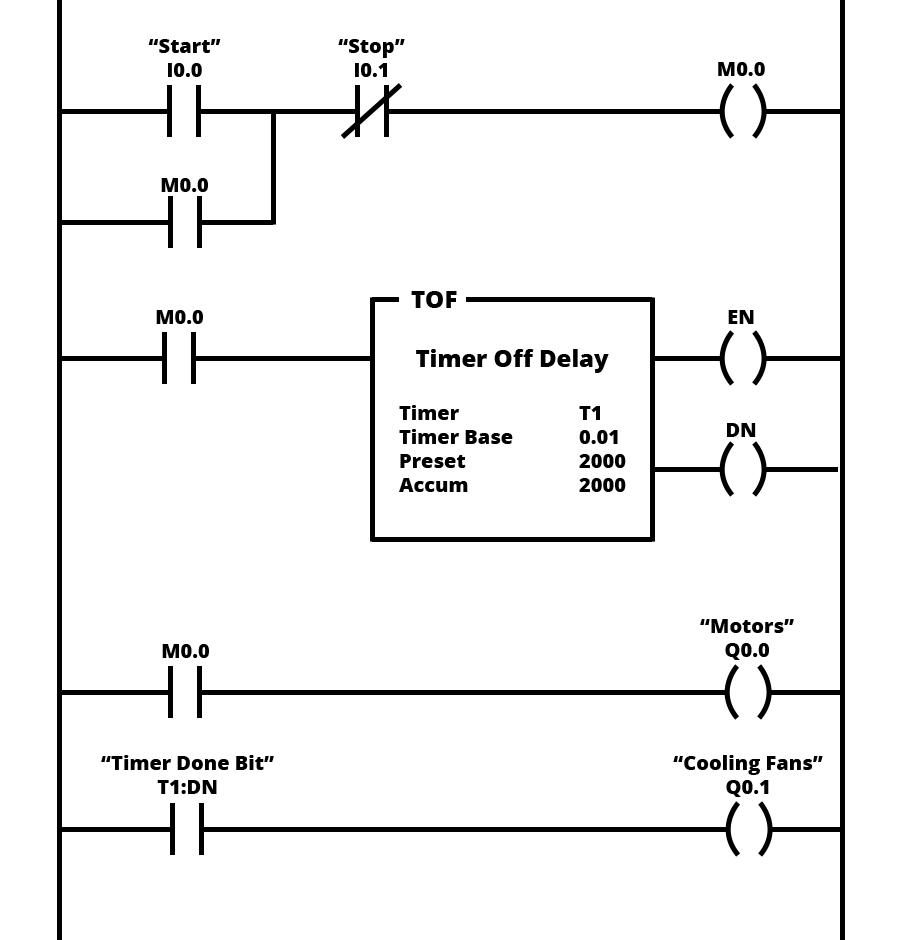
Motor control circuits are often con nected to lower voltages than the motor they control to make it safer for operators and maintenance personnel. The finished project contains electrical diagrams panel mechanical layout and various lists. If you keep the word switch in mind it helps keep the intimidat ing. In ladder diagrams the load device lamp relay coil solenoid coil etc is almost always drawn at the right hand side of the rung. Tutorial motor control o shows you how to make a small control circuit where all components are found in the component database. The interlock contacts installed in the previous sections motor control circuit work fine but the motor will run only as long as each push button switch is held down.
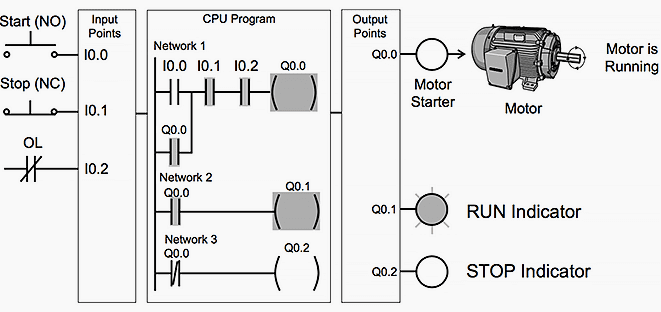
We could replace the push button switches with. In the following example a normally open start pushbutton is wired to the first input i00 a normally closed stop pushbutton is wired to the second input i01 and normally closed overload relay contacts part of the motor starter are connected to the third input i02. Upgrading a machine to plc control may seem like a daunting task. Assortment of plc panel wiring diagram pdf.
Gallery of Motor Control Circuit Diagram With Plc Pdf