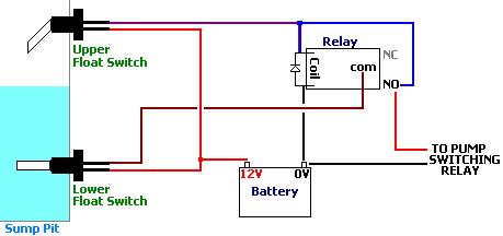
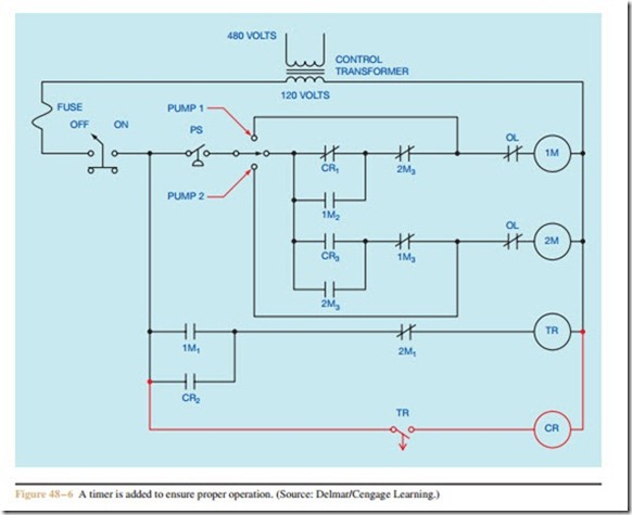
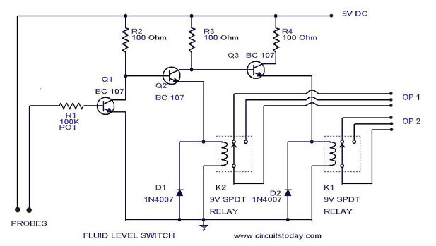
However with the pressure switch the pump can be adjusted to turn on and off at predetermined settings to control the pump and subsequent pressure. One set of relay contacts connects the pump to the supply and the other maintains the relay on state while the level.

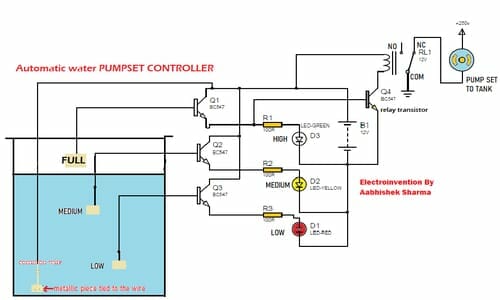
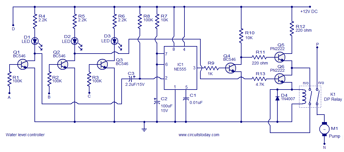
Simple Automatic Water Pump Controller Circuit Diagram
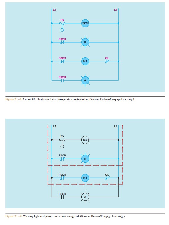
Pump control circuit diagram. It works off a 12v dc power supply and consumes very little power. The liquid rises until the top float switch closes and energises the relay. Without the use of the switch the water pump would always be on or off. The circuit will automatically switch on any water pump motor when the level of water in a tank reaches below from the required level and automatically switch off the pump after filling the tank. 3 phase submersible pump control panel circuit diagram 3 phase submersible pump wiring diagram single phase water pump motor wiring diagram how to connect submersible pump wires. Automatic water pump controller circuit.
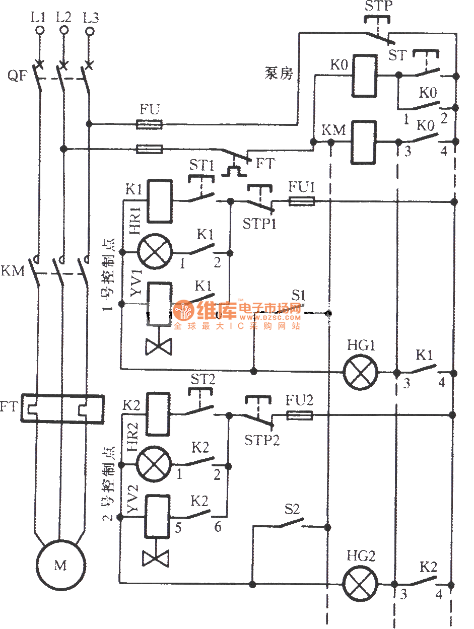
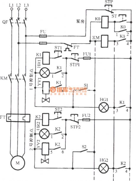
Here is the complete guide step by step. The wiring connection of submersible pump control box is very simple. Built around only one nand gate ic the circuit is simple compact and economical. Jun 19 2017 single phase 3 wire submersible pump control box wiring diagram or single phase submersible pump starter wiring diagram and wiring installation guide. This diagram is for the circuit to empty a tank using two normally open float switches and a two pole changeover relay. The circuit can be divided into two parts.
The bottom switch will be closed provided the liquid is above that switch point. 1 shows the controller circuit. Single phase submersible pump control box wiring diagram 3 wire submersible pump wiring diagram in submersible pump control box we use a capacitor a resit able thermal overload and dpst switch double pole single throw. The circuit can be used for variety of purposes like filling pools tanks container washing machines etc. And it can not only use for controlling. Controller circuit and indicator circuit.
Pressure switches are used on water pumps for the accurate control of the pump as it produces pressurized water.
Gallery of Pump Control Circuit Diagram