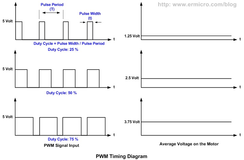
By varying r2 duty cycle can be varied from 0 to 100. Pwm motor speed control circuit diagram with parts list.

Dc Motor Speed Controller Pwm 0 100 Overcurrent Protection
Pwm motor control circuit diagram. 555 pwm circuit step by step setup tutorial. This is used to control the speed of a dc motor. The main component of this. Dc motor speed control using potentiometer with potentiometer and 555 timer ic. Today we are going to show you how to do dc motor control pwm with 555 timer ic. Are you fed up with ordinary pwm circuits which do not provide perfect dc motor speed control especially at lower speeds.
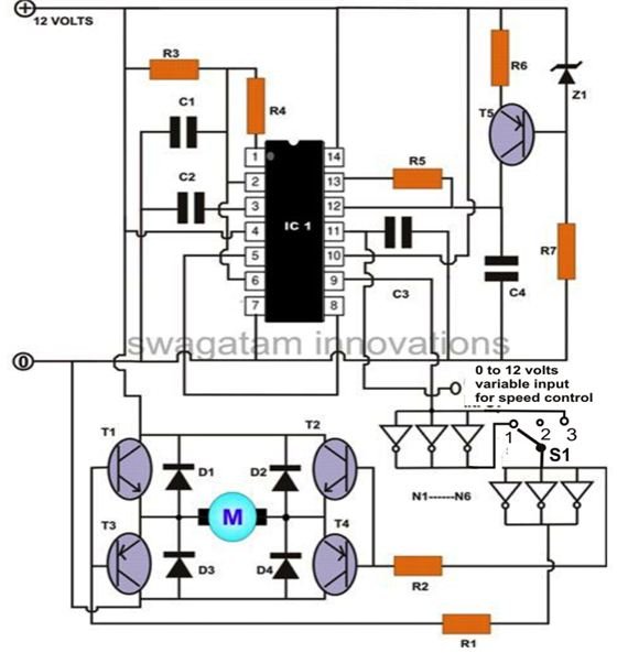
How the motor speed controller works in this circuit the ne555 timer ic is configured to generate square wave. Another popular application is motor speed control. Pwm is more effective at controlling motor speeds at low rpm than linear methods. Pin 3 of the ne555 timer. Then check out this outstanding single chip pwm motor speed controller circuit that will give you a complete 360 degrees of continuously varying motor speed control right from zero to maximum. Pwm is often used in conjunction with an h.
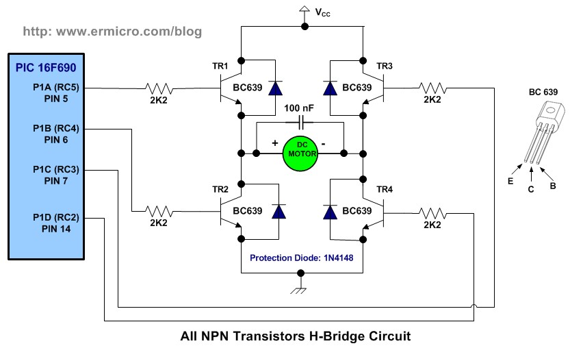
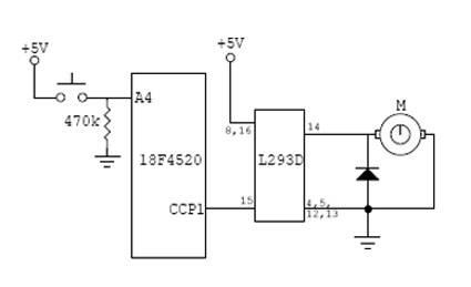
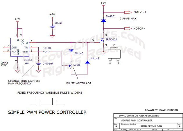
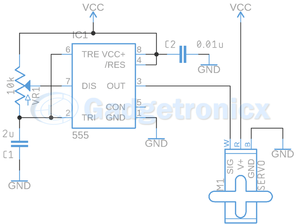
The speed is controlled through an externally applied varying dc voltage source. The circuit is very simple and can be built in very short time if all parts are available with you. A circuit which enables a user to linearly control the speed of a connected motor by rotating an attached potentiometer is called a motor speed controller circuit. Dc motor speed control circuit diagram we have used pic16f876 microcontroller to generate pwm and to change the duty cycle by reading the analog value of voltage across the variable resistor. For identifying pins of sl 100 the pin that is connected to casing is collectorthe pin near to notch is emitter and the one remaining is base. Following is a working circuit diagram of the ne555 pwm based dc motor speed controller.
Motors as a class require very high currents to operate. Being able to vary their speed with pwm increases the efficiency of the total system by quite a bit. Wiring diagram parts list design worksheet duration. Pwm motor speed control circuit diagram. 3 easy to build speed controller circuits for dc motors are presented here one using mosfet irf540 second using ic 555 and the third concept with ic 556 featuring torque processing. This simple dc motor control or pwm circuit using 555 ic can be used to control the speed of a dc motor.
We can use any microcontroller you want. The capacitor c2 gets changed and discharged through the output pin ie. The heart of the circuit is a ne555 timer ic which is working as a astable multivibrator here.
Gallery of Pwm Motor Control Circuit Diagram