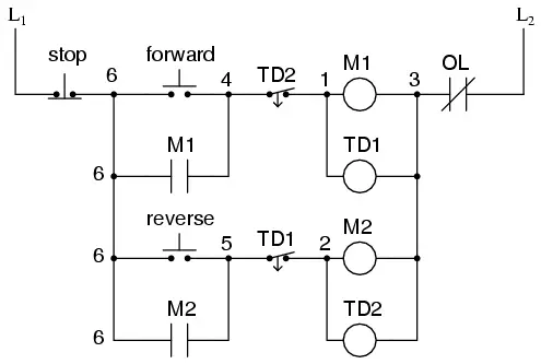
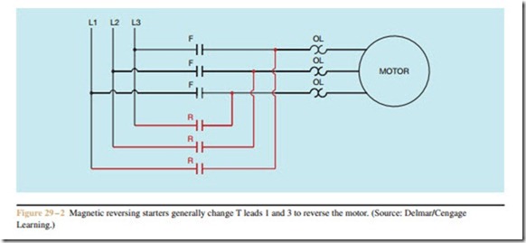
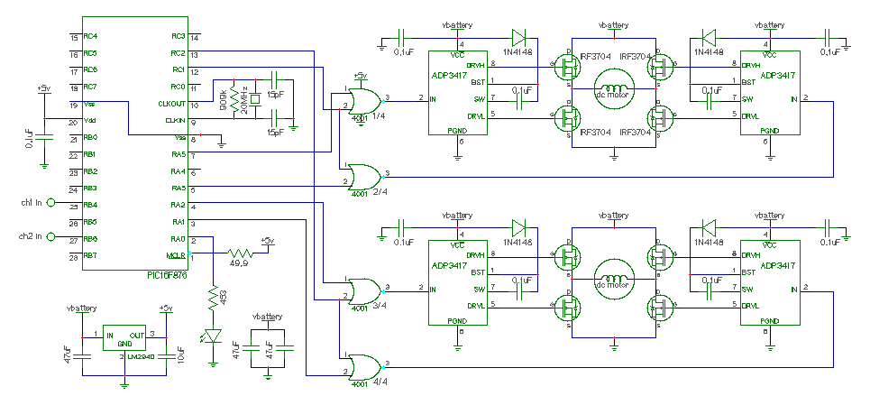
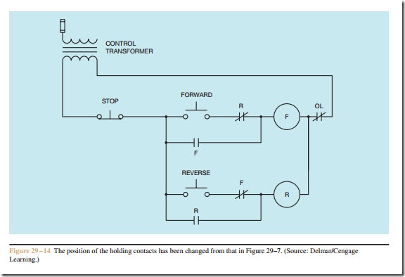
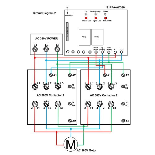
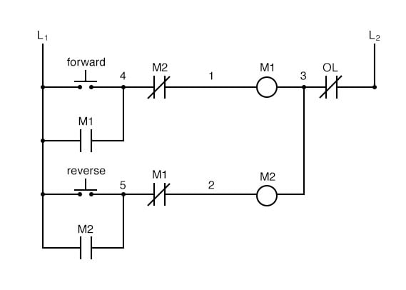
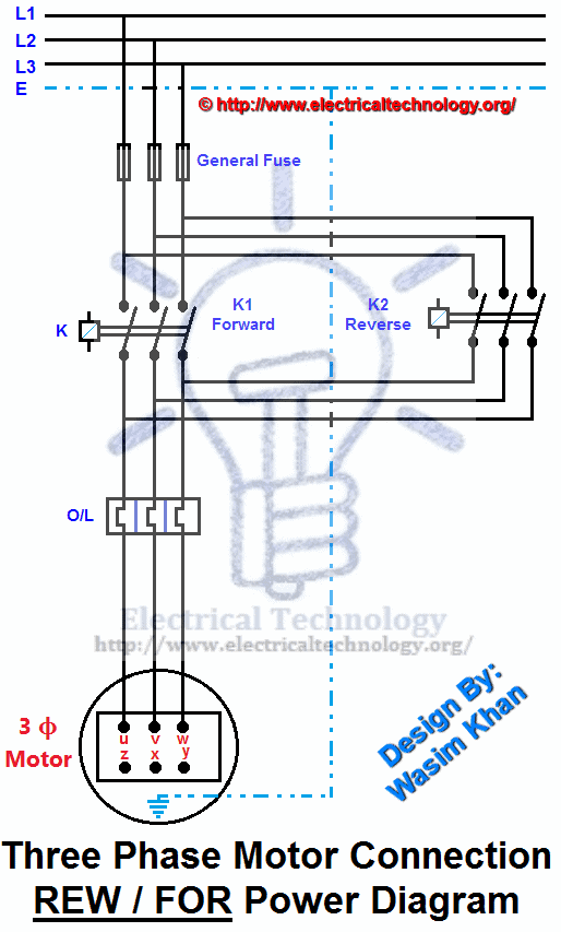
How to read an electrical diagram lesson 1 duration. The figure given below shows the control and power diagram of forward and reverse starter diagram.

3 Phase Wiring Diagrams Archives Electrical And Electronics
Reverse forward control circuit diagram. Delta connection electrical circuit diagram ohms law electrical installation electrical engineering electronics projects computer science alcohol dispenser electrical wiring diagram. In the below main wiring diagram. Control circuit of forward reverse starterpdf you may also like. Forward reverse 3 phase ac motor control circuit diagram electrical engineering updates. We use 2 magnetic contactors as forward reverse switch. A wiring diagram is a simplified conventional pictorial representation of an electrical circuit.
Figure 5 forwardreverse motor wiring diagram. Reverse forward motor starter control and power circuit with diagram motor windingstar delta starterdol starterstar delta connection3 phase dol starter connection diagram direct online starter. To run the motor of above 05 hp rating circuit has to made in star delta. Variety of single phase motor wiring diagram forward reverse. Control circuit for forward and reverse motor checkout video on 4 way switch wiring. Forward reverse motor control diagram for three phase motor for three phase motor forward reverse control circuit.
There is problem in control drawing because when motor runs forward or reverse then we can not change its state to forward or reverse by its push button. I convert the diagram in two parts for better understanding. Reverse forward motor control circuit diagram for three phase motor. Direct start 2 directions of rotation. It reveals the components of the circuit as simplified forms as well as the power as well as signal links in between the tools. In this wiring diagram both the forward and reverse coils have their returns connected to l2 and not to the overload contacts.
In the event of an overload both motor starter output. The overload contacts are connected to l1 on one side and to the plcs input module on the other input 003. In the diagram i connect the incoming three phase supply l1 l2 l3 to the mccb circuit breaker molded case circuit breaker. These forward and reverse starters are dol type and not used above the 05 hp motors. Here first i am sharing with the main wiring diagram. Control circuit of dol starter control circuit of fully automatic starter auto transformer working and saving in copper material speed control of dc series motor.
I shown the complete method. The supply can not the the other conductor because nc and no both are open. These type of starters are used in various applications eg mixing of materials dying. The three phase incoming supply molded case circuit breaker mccb two magnetic contactors. Here i showed the forward reverse wiring diagram.


