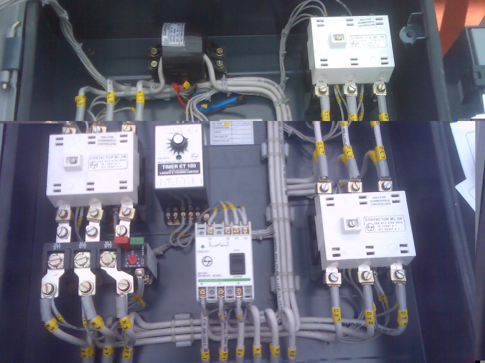
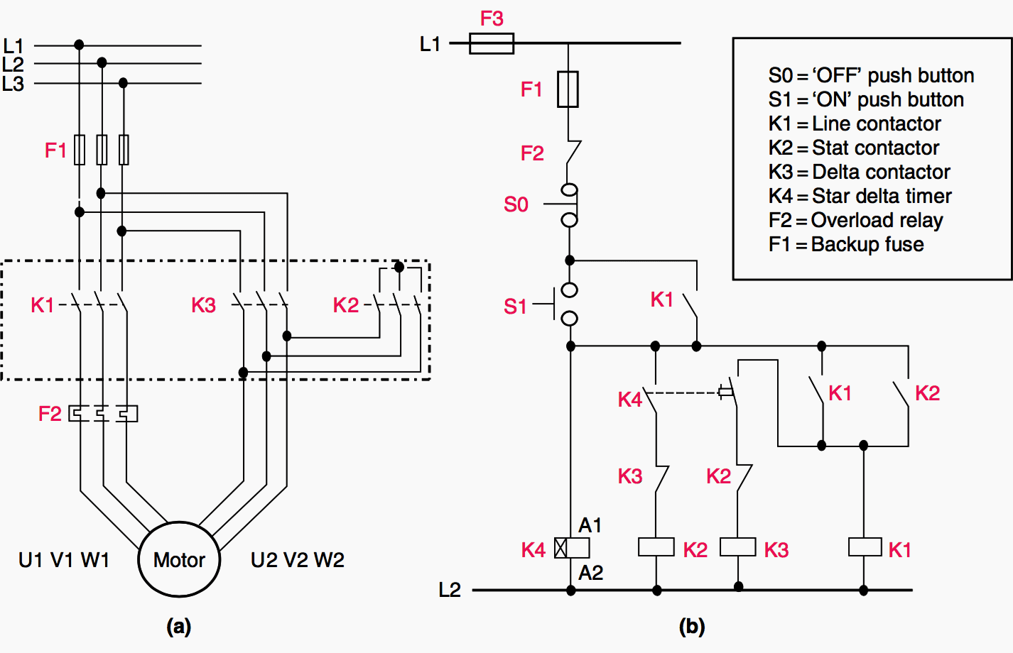
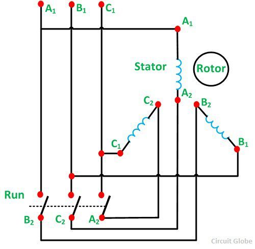
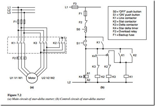
Here the circuit diagram of star delta starter explained in detailhere you will learn the connection of star delta starter with three phase motorthe power circuit diagram and control circuit diagram of an automatic star delta starter are explained belowlets understand the star delta starter diagram. In the above star delta starter control circuit wiring diagram with timer and normally close push buttonnormally open push button switch.
Troubleshooting Control Circuits Basic Control Circuits
Star delta control circuit diagram with timer pdf. Star delta wiring diagram electrical engineering updates. A 8 pin timer are used. Refer to the below star delta circuit. In control wiring diagram all magnetic contactors coils are rated 220 vac. When star contactor coil km1 energized star main and auxiliary contactor change its position from no to nc. Star delta connection circuit diagram.
In control wiring diagram all magnetic contactors coils are rated 220 vac. The on delay timer diagram is also shown in the diagram. Star delta starter control circuit diagram is today topic. Star delta starter control circuit diagram. The power circuit uses to create contact between the motor and three phase power supply. The control circuit uses to control the starter circuit such as on off and tripping operations.
Scheme control circuit of star delta starter open transition the on push button starts the circuit by initially energizing star contactor coil km1 of star circuit and timer coil kt circuit. Star delta starters consist of a power circuit and control circuit. In the above star delta starter control circuit wiring diagram with timer and normally close push buttonnormally open push button switch. In this tutorial we will show the star delta y δ 3 phase induction ac motor starting method by automatic star delta starter with timer with schematic power control and wiring diagram as well as how star delta starter works and their applications with advantages and disadvantages.
