C i m nc. The trigger condition takes priority over the break condition the startstop circuit is stop dominant.
Start Stop Circuit Contact And Coil
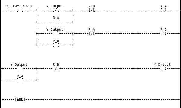
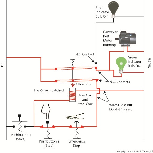
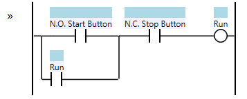
Start stop motor control ladder diagram. This pattern is an extension to the sealed in coil pattern and is similar to the state coilhowever where the state coil is trigger dominant ie. In fact the plc is a common choice for controlling ac motors. In the normal state push button 1 is open and push button 2 closed. Here are some examples of ladder diagrams for motor control. Ladder diagram basics 3c 3 wire control duration. Ladder diagram basics 3 2 wire 3 wire motor control circuit duration.
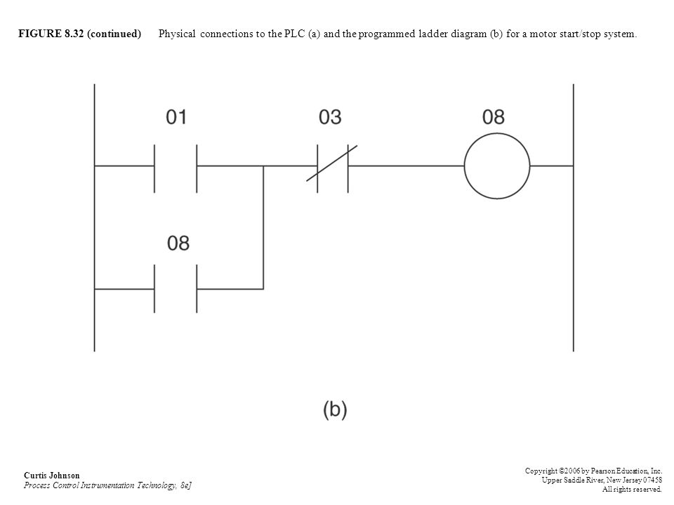
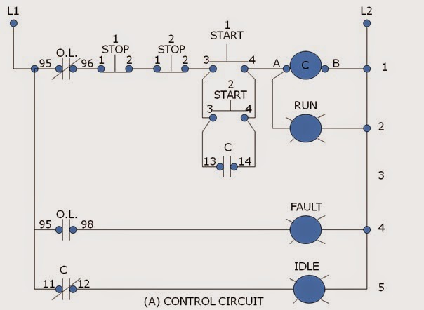
Dol starter is used for the motors having rating upto the 05hp. Pilot light l2 4 2 3 pilot light start stop bulletin 1495 normally closed auxiliary contacts are required. With ladder diagrams no attempt is made to show the actual physical locations and the emphasis is on clearly showing how the control is exercised. T w 6. 1 ladder logic to startstop motor using only one momentary no push button. Motor control can be done with a plc program.
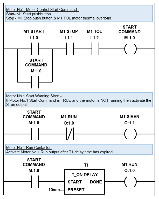
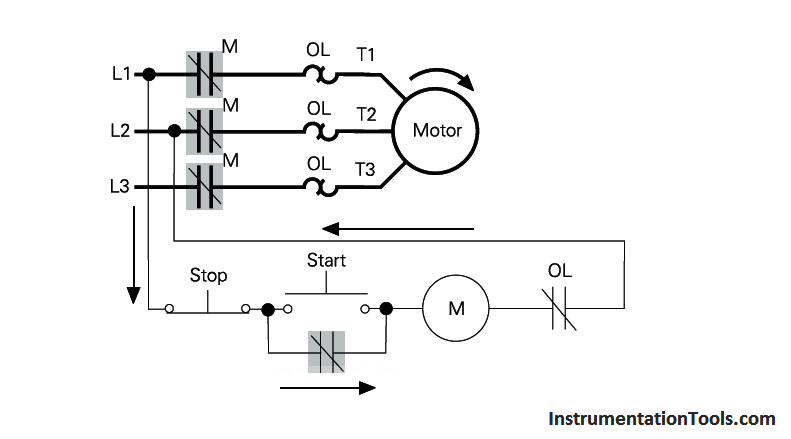
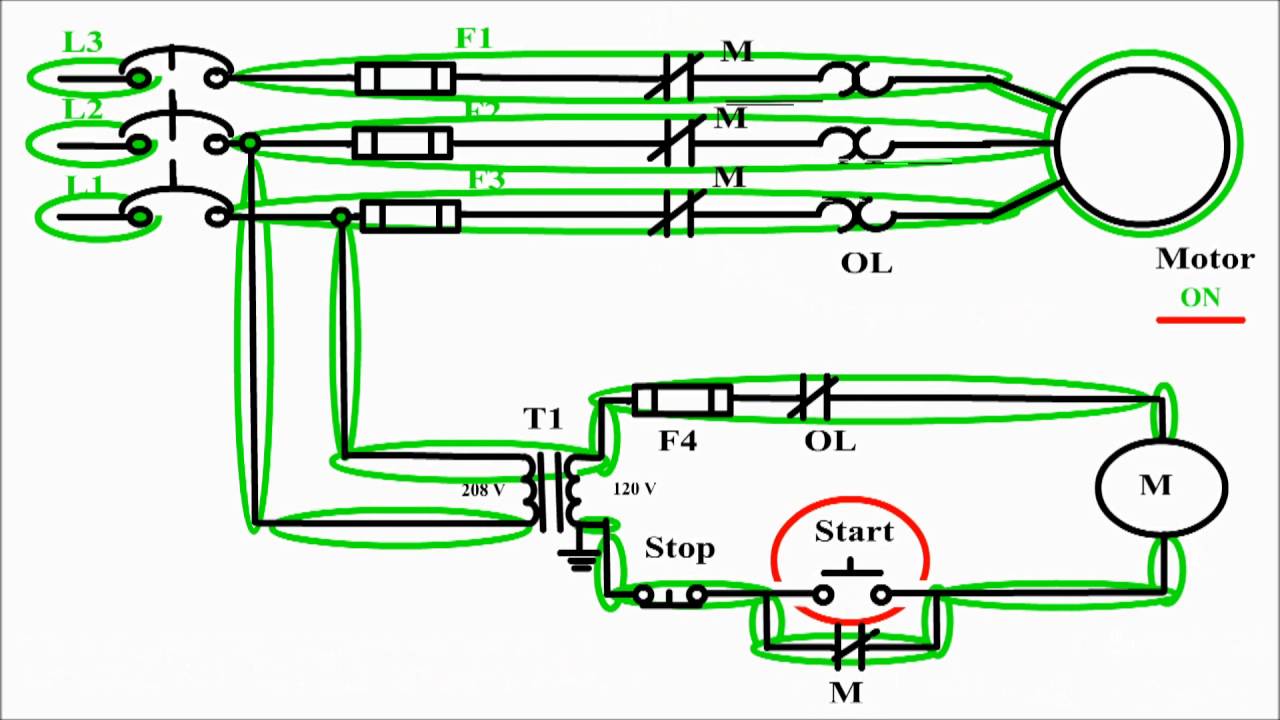
Motor contactor or starter coils are typically designated by the letter m in ladder logic diagrams. One of the most common ways to start an ac motor is by first starting the motor in star connection. Ladder diagram for motor control. Continuous motor operation with a momentary start switch is possible if a normally open seal in contact from the contactor is connected in parallel with the start switch so that once the contactor is energized it. Star delta plc ladder diagram. For push button control stations 7 start stop control wiring diagrams single station with motor stopped pilot light l1 start l2 i 1 stop 2 oi 3 n wol.
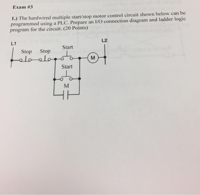
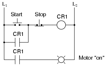
A very useful ladder logic programming pattern is the startstop circuit. Pete vree 332205 views. Ladder diagram basics 4 multiple stop start stations duration. This video builds on the standard 3 wire circuit by incorporating multiple stopstart stations. Can anybody do this for me. With the switch closed the control circuit acts as a normal stopstart station controlling a load connected to the pilot device power is sitting on the start and seal in terminals of the pushbutton.
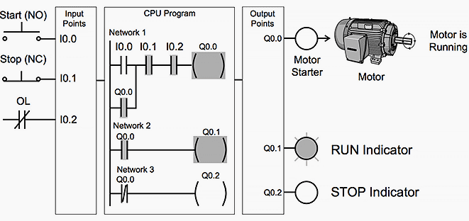
Pressing start immediately sends power through the start pushbutton and the seal in contacting energizing the coil. In the previous article we have learned about the control diagram of the dol starter and now in this article we will learned about the ladder diagram of the dol starterdol direct on line starter is used to start the motor by applying full line voltage to the motor. With the motor running contacts are open. Figure 2 see below shows an example of a ladder diagram for a circuit that is used to start and stop a motor using push buttons.
Gallery of Start Stop Motor Control Ladder Diagram