A wiring diagram is a simplified standard pictorial representation of an electrical circuit. It is often called a stepper motor driver.

Controlling A Stepper Motor With An Arduino 8 Steps With
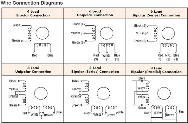
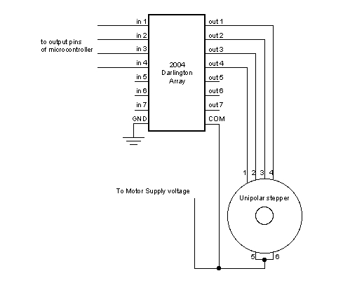
Stepper motor diagram. A stepper motor driver or stepper motor drive is a circuit which is used to drive or run a stepper motor. Stepper motor driver circuit diagram and explanation. A stepper motor or a step motor is a brushless synchronous motor which divides a full rotation into a number of steps. A stepper motor driver usually consists of a controller a. The motor has six wires connected to two split windings as is common for unipolar stepper motors. Stepper motor wiring diagram elegant ponent series circuit diagrams.
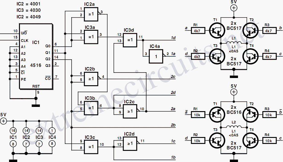
Assortment of stepper motor wiring diagram. A stepper motor or a step motor is a brushless synchronous motor which divides a full rotation into a number of steps. The circuit diagram for the arduino stepper motor control project is shown above. Stepper motor wiring diagram elegant ponent series circuit diagrams. These stepper motors consume high current and hence a driver ic like the a4988 is mandatory. Stepper motors work on the principle of electromagnetism.
A stepper motor also known as step motor or stepping motor is a brushless dc electric motor that divides a full rotation into a number of equal steps. To energise the four coils of the stepper motor we are using the digital pins 8910 and 11. Stepper motor is a type of brushless dc motor that converts electrical pulses into distinct mechanical movements ie. How to use 28 byj48 stepper motor. Now as shown in the circuit diagram the 555 circuit here is to generate clock or the square wave. Stepper motor control using arduino is a simple project where a bipolar stepper motor is controlled using arduino uno.
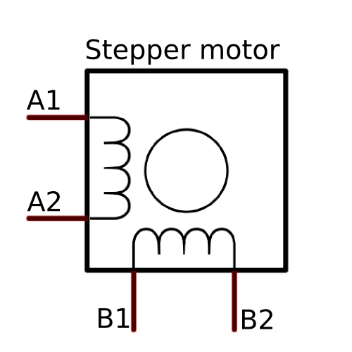
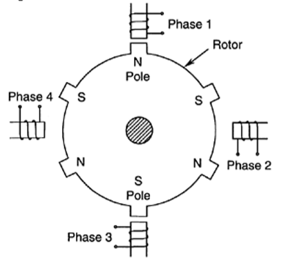
What is stepper motor driver. The motors position can then be commanded to move and hold at one of these steps without any position sensor for feedback an open loop controller as long as the motor is carefully sized to the application in respect to torque and speed. Stepper motor wiring diagram sample stepper motor wiring diagram elegant ponent series circuit diagrams. Arduino stepper motor control circuit diagram and explanation. To know how to make this motor rotate we should look into the coil diagram below. There is a.
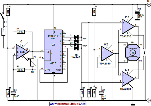
The figure shows the circuit diagram of two stage stepper motor driver. The shaft of a stepper motor rotates in discrete steps. Unlike a brushless dc motor which rotates continuously when a fixed dc voltage is applied to it a step motor rotates in discrete step anglesthe stepper motor can be controlled with or without feedback. Easy to build cnc mill stepper motor and driver circuits 6 steps. It shows the components of the circuit as simplified forms as well as the power and also signal links in between the tools. Unlike a brushless dc motor which rotates continuously when a fixed dc voltage is applied to it a step motor rotates in discrete step angles.
The frequency of clock generation in this case cannot be kept constant so we need to get variable speed for the stepper motor. Stepper motor driver circuit diagram schematic march 15 2020 february 24 2012 by electrical4u. We have used the 28byj 48 stepper motor and the uln2003 driver module.


