Thermal contacts tb white m 1 z2 yellow z1 blue u2 black u1 red bridge l1 and l2 if speed controller sc is not required m 1 ln e white brown blue l1 l2 n sc. With single phase motor with capacitor forward and reverse wiring.

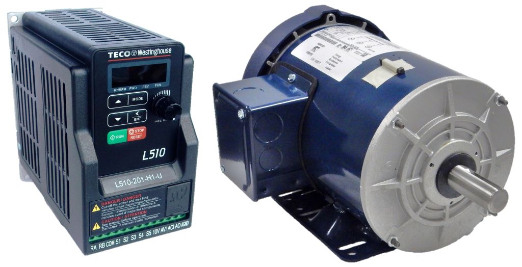
L510 201 H1 U Teco 1 Hp 230v 1 Phase Input 4 3 Drive Amps Constant Torque
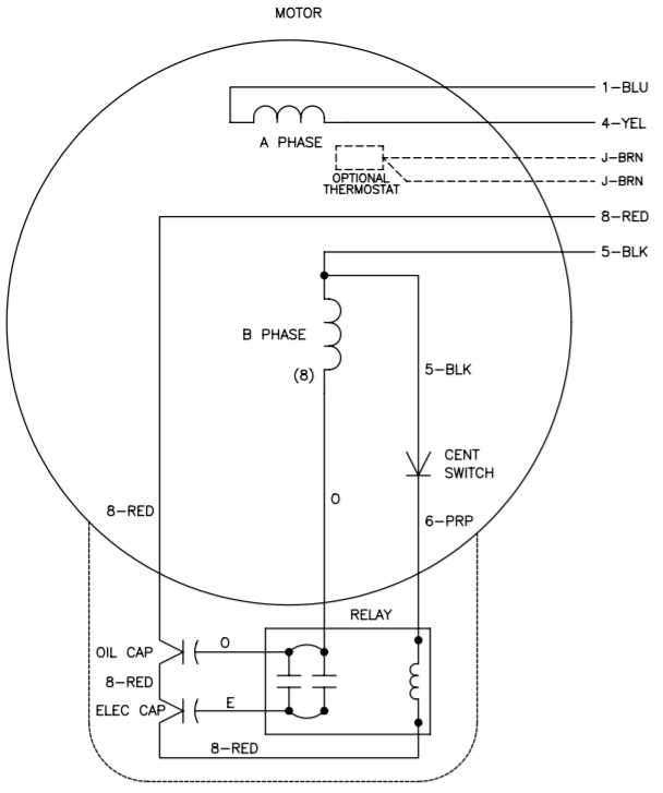
Teco single phase motor wiring diagram. Learn how a capacitor start induction run motor is capable of producing twice as much torque of a split phase motor. Click here to view a capacitor start motor circuit diagram for starting a single phase motor. This type of motor is designed to provide strong starting torque and strong running for applications such as large water pumps. Hvac single phase odp product description 640kb single phase tefc. Wondering how a capacitor can be used to start a single phase motor. W2 cj2 ui vi wi w2 cj2 ui vi wi a cow voltage y high voltage z t4 til t12.
Farm duty single phase product description 685kb. Capacitor motor single phase wiring diagrams always use wiring diagram supplied on motor nameplate. Single phase motor wiring diagram with capacitor sources. Also read about the speed torque characteristics of these motors along with its different types. In this video jamie shows you how to read a wiring diagram and the basics of hooking up an electric air compressor motor. Single phase motors are used to power everything from fans to shop tools to air conditioners.
Single phase motor wiring diagram forward reverse collections of phase meter wiring diagram single phase motor capacitor wiring. Installation and maintenance instructions for three phase induction motors 364kb beyond premium efficiency motor solutions 396kb max pm permanent magnet motors 425kb single phase motors single phase odp. These tips can be used on most electric motor brands such as weg baldor. Wiring diagram for single phase motor fresh pretty single phase. Induction motor totally enclosed fan cooled nema standard epact three phase induction motors sdesign versatility teco totally enclosed fan cooled squirrel cage induction motors are designed manufactured and tested to meet or exceed the latest nema ieee csa and. Diagram dd6 diagram dd7 m 1 ln e diagram dd8 ln e l1 l2 l3 sc z1 u2 z2 u1 cap.
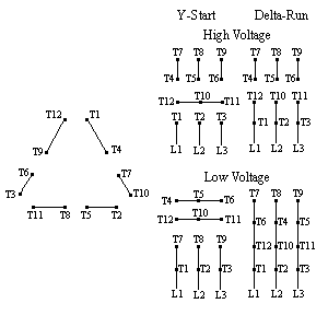
For all other single phase wiring diagrams refer to the manufacturers data on the motor. Always use wiring diagram supplied on motor nameplate for motors with thermal protection single voltage single rotation single voltage reversible rotation. Residential power is usually in the form of 110 to 120 volts or 220 to 240 volts. Teco australia new zealand head office 335 337 woodpark road smithfield nsw 2164 phone 61 2 9765 8118 fax 61 2 9765 8185 email. Capacitor start capacitor run induction motors are single phase induction motors that have a capacitor in the start winding and in the run winding as shown in figure 12 and 13 wiring diagram. Wiring a motor for 230 volts is the same as wiring for 220 or 240 volts.
.jpg)






_main.jpg?width=800&height=800&ext=.jpg)
