Some 555 versions may get damaged because of this. To prevent 555 timer from flyback current in the relay use a diode before the relay.

Icm Timer Wiring Diagram Honda 10 Brillenstudio Weichert De
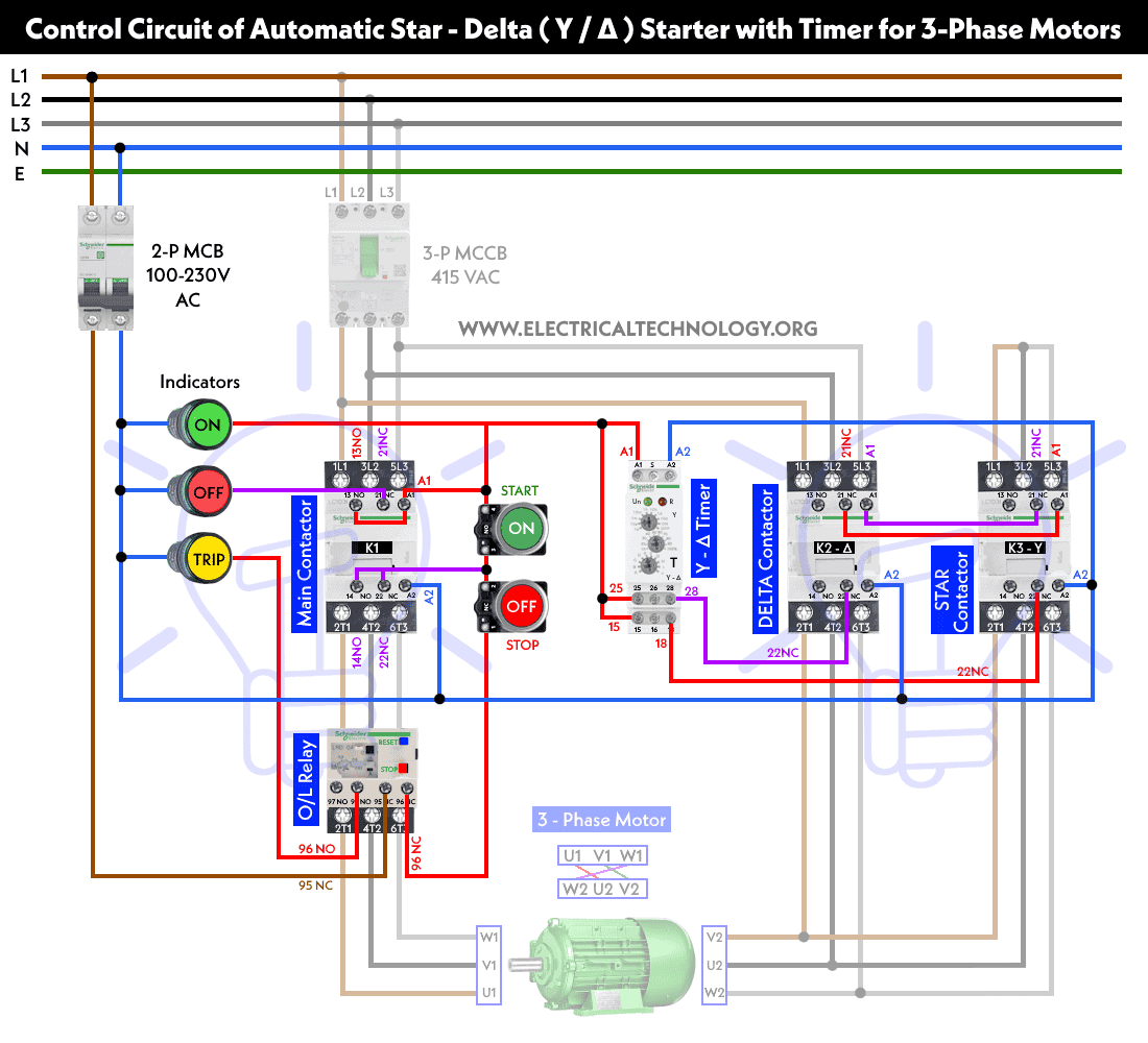
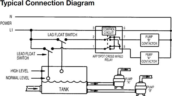
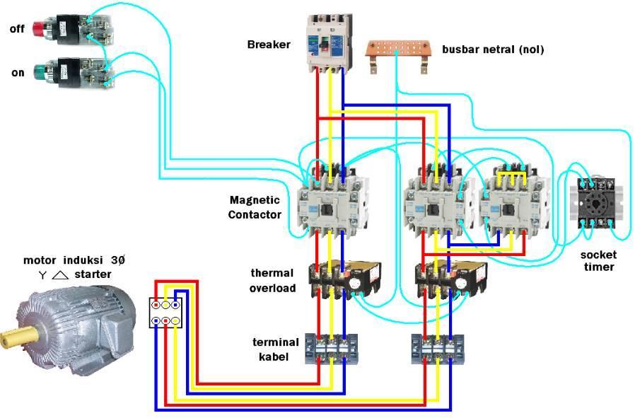
Timer relay contactor wiring diagram. Working diagram of relay. Three phase dol starter control overload indicator power wiring diagram duration. Relay contactor wiring diagrams 156 b30ab1 datasheet cross reference circuit and application notes in pdf format. Clap switch circuit using ic 555 timer without timer. A simple circuit diagram either of the two start buttons will close the contactor either of the stop buttons will open the contactor. 12v time delay relay adjustable on off timerusing 555 astable mode in this circuit a timer with cyclic on off operations is designed.
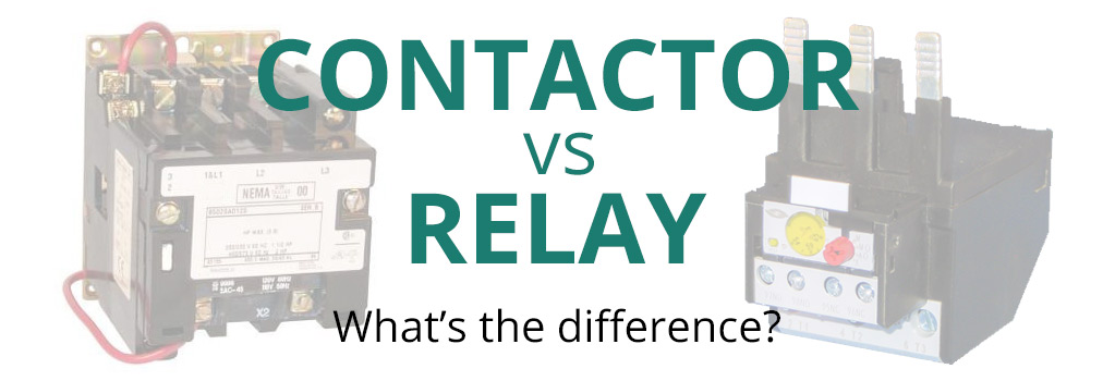
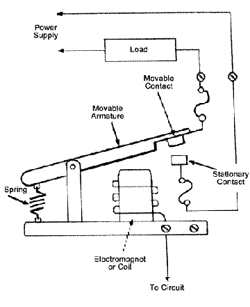
Contactor working principle of contactor is same as relay but it mainly uses for heavy duty work. Easy and simple wiring diagram to make you learn easily watch the video and subscribe my youtube channel air. Switch this element uses for interface between machine and human or operator. Catalog datasheet mfg type pdf document tags. These lines far exceed the 120 volts ac standard in most homes. Variety of 2 pole contactor wiring diagram.
On delay timer circuit diagram wiring diagram contactor with push button circuit diagram of delay timer on off power off delay timer circuit diagram 2 way lighting circuit triggering transformer push button fan switch light activated switch circuit diagram wd081 text. Many large pieces of equipment are powered directly from high voltage lines. Overload relay 1ct m m motor 3ct to 120 v separate control ot is a switch that opens. Contactor switching time is higher than relay. There are many type of button as momentary switch selector switch. Contactor breakers limit switch no static control.
240 volts ac and 480 volts ac are commonly used for these large pieces of. Each component should be placed and linked to other parts in particular manner. It reveals the components of the circuit as streamlined forms and the power and signal links in between the tools. Star delta timer d delay contactor block timer in mechanical type tamil etech world. Electrical earthing methods and types of earthing grounding. Wiring diagram since wiring connections and terminal markings are shown this type of diagram is helpful when wiring the.
A wiring diagram is a simplified traditional photographic depiction of an electrical circuit. Sdt 20 thermistor klixon start relay motor sdt 100 thermistor sdt 1000 thermistor star delta timer starter diagram str 421 230v latching relay dpdt 12v. Dol starter control and power wiring by using a fuse contactor overload relay motor. How to wire a contactor.

