That said for specific situations there are industrial standards with different connectors and wire arrangements. There is additional wiring involved in tying your braking system and battery power to the rear plug which activates the trailer brakes when you depress your brake pedal.

Trailer Brake Controller Installation How To 5 Easy Steps
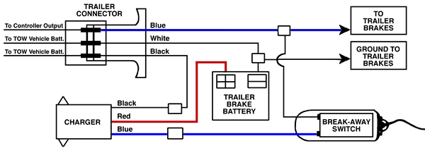
Trailer brake box wiring diagram. As the name implies they use four wires to carry out the vital lighting functions. Plugs into the existing 4 way. The trailer brakes are activated electronically by the use of a brake control box mounted under the dash in the tow vehicle. Return to the duplex cable under the hood where the brake wire now white needs to be separated from the 12 volt hot lead black. An extra pin allows using another extra function. This guide will be discussing trailer breakaway box wiring.
Trailer breakaway box wiring diagram trailer brake battery box wiring diagram trailer brake box wiring diagram trailer breakaway box wiring diagram folks understand that trailer is a vehicle comprised of very complicated mechanics. 5 way trailer wiring diagram allows basic hookup of the trailer and allows using 3 main lighting functions and 1 extra function that depends on the vehicle. 4 way trailer connectors are. 4 way trailer connectors are typically used on small trailers such as boat snowmobile utility and other trailers that that do not use brakes. A wiring diagram is a streamlined conventional pictorial representation of an electric circuit. If your vehicle is not equipped with a working trailer wiring harness there are a number of different solutions to provide the perfect fit for your specific vehicle.
The following trailer wiring diagrams and explanations are a cross between an electrical schematic and wiring on a trailer. Drive a crew cab extended cab with long bed cargo van or extended length suv extra wire etbcxw sold separately will make installation much easier. Complete with a color coded trailer wiring diagram for each plug type this guide walks through various trailer wiring installation solution including custom wiring splice in wiring and replacement wiring. We recommend these standards because they are pretty universal. This automobile is designed not just to travel one place to another but also to carry heavy loads. Assortment of electric trailer brake wiring schematic.
This universal wiring kit lets you install an electric brake controller sold separately in your vehicle and a 7 way connector for your trailer lights at the same time. The four wires control the turn signals brake lights and taillights or running lights. Secure the brake controller into the mounting bracket. It reveals the parts of the circuit as streamlined forms as well as the power and signal connections in between the gadgets. 5 wire trailer wiring diagram. Trailer wiring diagrams trailer wiring connectors various connectors are available from four to seven pins that allow for the transfer of power for the lighting as well as auxiliary functions such as an electric trailer brake controller backup lights or a 12v power supply for a winch or interior trailer lights.
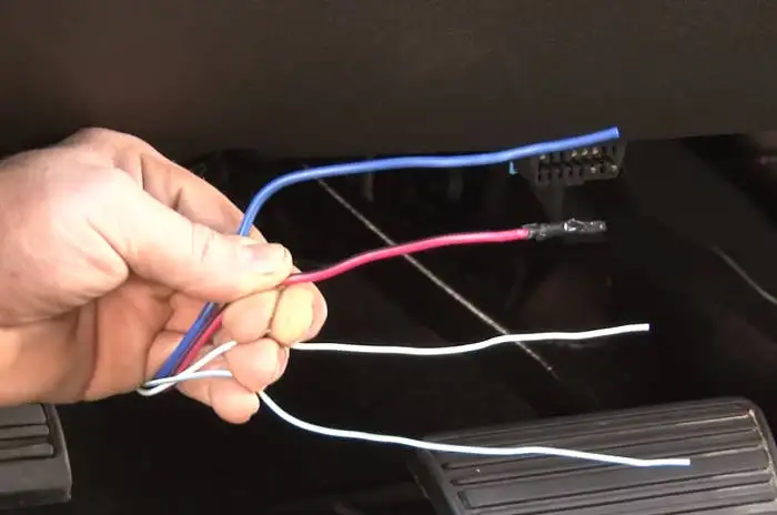
The four wires on the brake controller will be connected shortly. Wiring the 7 way trailer connector and brake controller. They also provide a wire for a ground connection.


