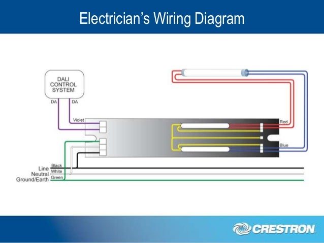
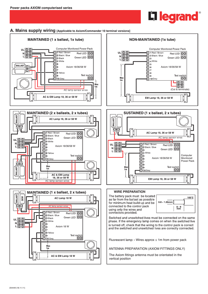
Universal wiring diagram for hf ballasts the following wiring instructions apply to any existing luminaire containing a hf ballast to be converted to 1 hour or 3 hour maintained luminaires depending on model. Wiring diagrams and installation examples page 14 em basic 230 240 v 5060 hz basic version tc del tc l tc dd tc sel tc tel t5 t8.

Advance Dimming Ballast Wiring Diagram Wiring Diagrams
Tridonic ballast wiring diagram. Properties of tridonic em basic ballasts. Certificates data sheets environmental declarations operating instructions etc. Overview of technical documents as pdf grouped according to topics eg. 3 hour rated duration can be used with all electronic ballasts both dimmable and non dimmable suitable for use in combination with magnetic ballasts 5 pole technology 4 pole lamp changeover and delayed power switching to. Switching for the ballast optimised ac output voltage for tc dd and tc l lamps. In case of larger installations power supply for the ballasts can be subdivided into several conductors l1 l2 l3.
This video is about the how to connect led emergency lights and lamps driver tridonic ballast wiring connection complete guide in urduhindi language is video main ap dosto ko bataun ga ke saudi. Subect to change without notice. Step 1 remove the switched line from the ballast and wire to the lin terminal of the emergency module. As a leading global provider of smart and efficient lighting solutions tridonic empowers its customers and business partners to become more successful by making professional lighting smarter more exciting and more sustainable. The tridonic em 34b basic is an emergency lighting supply unit for linear and compact fluorescent lamps from 18 to 58 watts. In case of five pole wiring it is recommended to connect the neutral conductor to d1 to prevent that 400 v are applied between adjoining terminals if a different conductor is used for the control input.


