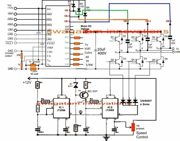
A well calculated 3 phase signal is applied across the hin123 and lin123 inputs of the ic through a 3 phase signal generator stage. Here mcb uses to control the input supply into the circuit.
How To Make A 3 Phase Vfd Circuit Homemade Circuit Projects
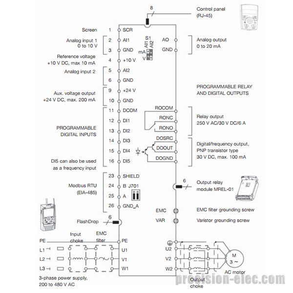
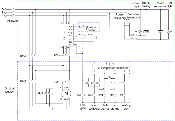
Vfd control circuit diagram. Check connections of l1 l2 l3. However operating motors under different input frequency conditions often becomes a compulsion and under such situations a vfd or a variable frequency drive circuit can become very handy. Rl1 and rl2 contacts should be taken from the vfd feedback relays. Mpcbmccb uses to control input supply of your vfd control the circuit by onoff the push button. Switch on the 3 phase power supply. The low side mosfetigbt gates are integrated with the ic2 pin3 of the above.
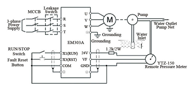
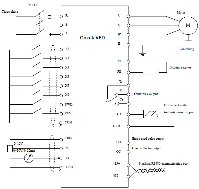
2 diagram shows an electronic diagram of a gozuk vfd. 2the filter section. A vfd is a device which allows the user to control the speed of an ac motor by adjusting the frequency and voltage of the input supply as per the motor. 3the switching or inverter section. Vfd circuit and its operation. T1 t2 t3 used for giving 3 phase input to vfd and connecting motor to it and wires coming out of m0 m1 and gnd.
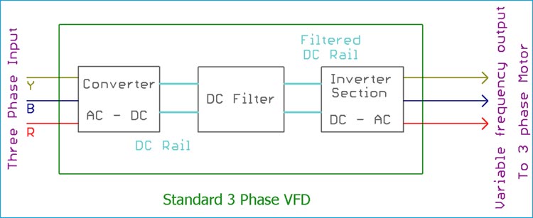
Pin out connection diagram for vfd m fig. Controlling a digital keypad on delta vfd m steps for complete motor control. In the below image the three sections are shown inside a block diagram. For programming the vfd m. The outputs of the ic irs2330 can be seen integrated with 6 mosfets or igbts bridge network whose drains are appropriately configured with the motor which needs to be controlled. 1 opened variable frequency drive for troubleshooting following fig.
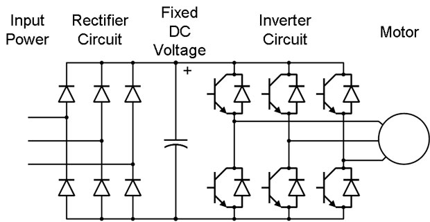
Rectifier section of vfd circuit rectifier section uses 6. 1the rectifier section. This is a basic circuit block diagram of a three phase vfd. The third block of the vfd is called the inverter section because this is where the dc voltage is turned back into three phase ac voltage. A vfd circuit consists of three parts. How does vfd start stop wiring diagram work.


