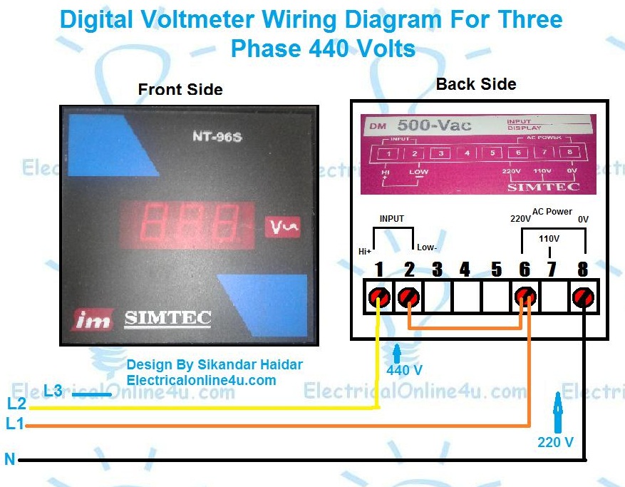
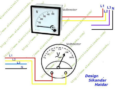
3 phase voltmeter connection diagram for line to line voltage testing 440v in a 3 phase analog voltage meter we have 2 terminals or contacts to provide the supply. Voltmeter gauge wiring diagram wiring diagram is a simplified customary pictorial representation of an electrical circuitit shows the components of the circuit as simplified shapes and the facility and signal contacts with the devices.
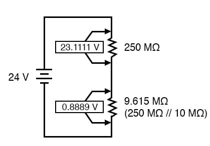
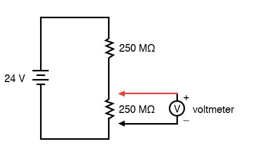
Voltmeter Impact On Measured Circuit Dc Metering Circuits
Voltmeter connection diagram. Connect the end coming from the steering column to the voltmeter. Voltmeter is useful in that it can give a warning of many electrical problems and can show many problems faster than an ammeter. In the above diagram i shown 3 phase 4 wire system supply but i only connect l1 and l2 read and yellow to the volt meter or voltage meter. Disconnect the batterys ground cable before working on the voltmeter. Use one of the wires that you found in the wiring harness and cut it between the steering column and connector in the dash. A wiring diagram is a simplified traditional photographic representation of an electric circuit.
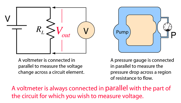
Butt connectors are stronger and more reliable but wire taps are faster and dont require cutting the original wire. Assortment of volt amp meter wiring diagram. Take the negative wire from the voltmeter and make a good connection on a grounded screw in the car. The voltmeter is a measuring device by which we can measure electrical pressure or. Key takeaways key points. The voltmeter connection can be made at the battery positive and negative if desired.
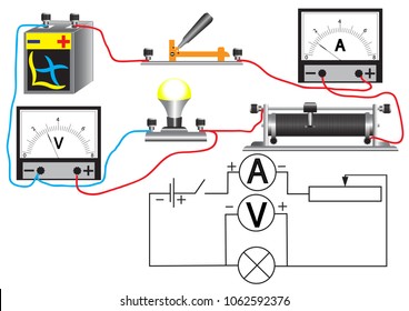
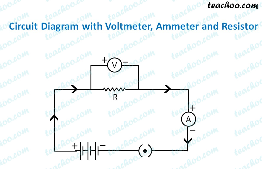
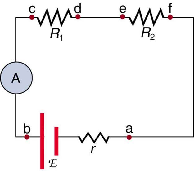
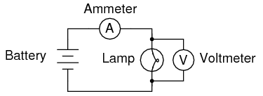
Today we are going to know the proper connection of ammeter and voltmeteralso we will discuss why ammeter is always connected in series and voltmeter in parallel. A voltmeter is an instrument used for measuring electrical potential difference between two points in an electric circuit. An ammeter is a measuring device used to measure the electric current in a circuit. The ammeter is connected in series for the measurement of current and the voltmeter is connected in parallel for the measurement of voltage. We can connect our single phase neutral and phase to these connects or connection point to measure the voltage between neutral and phase. Follow the instructions carefully for the se quenc e of nuts and washers on the connection posts of the voltmeter diagram 1.
Compare circuit connection of an ammeter and a voltmeter. Use either butt connectors or the commonly supplied wire taps to connect the voltmeter wires to the wiring harness. For three phase voltage meter you can only connect 2 line wire and if you connect the neutral and phase to the voltmeter then volt meter show the 220 voltage which is single phase voltage. Step 6 connect positive wire. It reveals the elements of the circuit as simplified forms and the power and signal connections between the devices.
Gallery of Voltmeter Connection Diagram