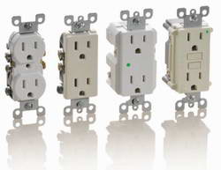
This is a polarized device. Standard wall outletreceptacle wiring.
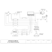
Receptacle Wiring Diagram Wiring Diagram
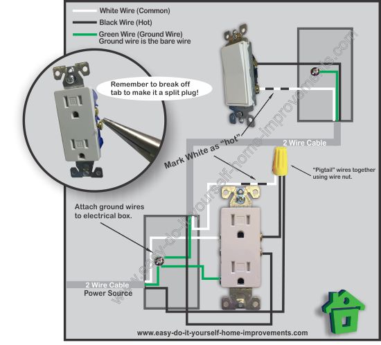
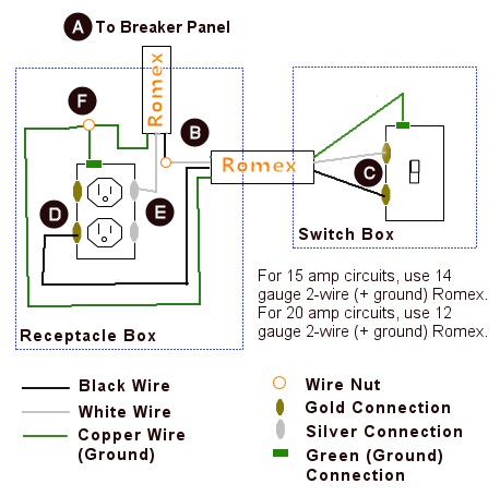
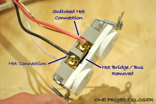
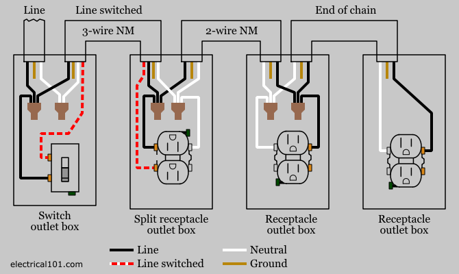
Wall outlet wiring diagram. Wiring diagram for a split outlet this diagram illustrates the wiring for a split receptacle with the top half controlled by sw1 and the bottom half always hot. If you add an outlet to a kitchen or bath it must be gfci protected. The black wire line and white neutral connect to the receptacle terminals and another 2 wire nm that travels to the next receptacle. The receptacle is split by breaking the connecting tab between the two brass colored terminals. Wiring outlets together using the device terminals instead of a pigtail splice as shown in the next diagram can create a weakest link problem. The hot black wire should connector to the brass colored screw.
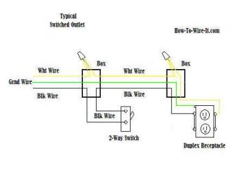
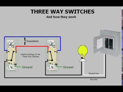
This switched outlet electrical wiring diagram shows two scenarios of wiring for a typical half hot outlet that can be used to control a table or floor lamp. The source hot wire is spliced with one of the switch wires and the other switch wire is connected to the hot line terminal on the device. Multiple outlet in serie wiring diagram. The long slot on the left is the neutral contact and the short slot is the hot contact. When wiring a wall outlet the neutral white wire should connect to the white or silver metal screw. This wiring diagram illustrates adding wiring for a light switch to control an existing wall outlet.
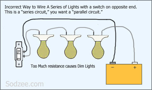
To wire multiple outlets follow the circuit diagrams posted in this article. For wiring in series the terminal screws are the means for passing voltage from one receptacle to another. Wiring diagram for a switched gfci combo outlet. There is a tab between each of the screws of similar color. The source neutral is connected the line neutral terminal. The source is at the outlet and a switch loop is added to a new switch.
The tab between the neutral silver terminals should remain intact. Any break or malfunction in one outlet will cause all the other outlets to fail. Wiring multiple outlets in a series in this diagram wall outlets are wired in a row using the terminal screws to pass voltage from one receptacle to the next. In the diagram below a 2 wire nm cable supplies line voltage from the electrical panel to the first receptacle outlet box. So before using the method we show here for how to wire a wall outlet in a kitchen or bathroom check with an electrical inspector. A grounded contact at the bottom center is crescent shaped.
This repeats until the end of the chain. The hot source wire is removed from the receptacle and spliced to the red wire running to the switch. The black wire from the switch connects to the hot on the receptacle. In this diagram the switch built into the combo device is wired to control the gfci outlet itself. The green screw obviously ties to the bare ground wire. Understanding switched outlet wiring for home electrical applications the switched outlet wiring configurations show two different wiring scenarios which are most commonly used.
Most electrical codes now require outlets in kitchens and bathrooms to be on separate 20 amp gfci circuits. This is a standard 15 amp 120 volt wall receptacle outlet wiring diagram.
Gallery of Wall Outlet Wiring Diagram