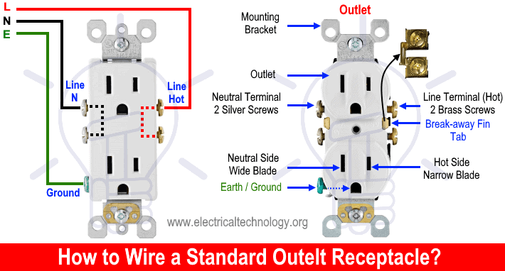
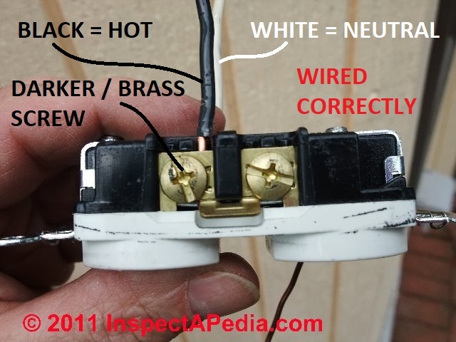
Attach the black wire to the bottom brass lug on the outlet. Run the new cable with sheathing at least two inches up inside the box and double over the excess wires to help hold the cable in place.

Tracing 3 Wire Circuits Jlc Online
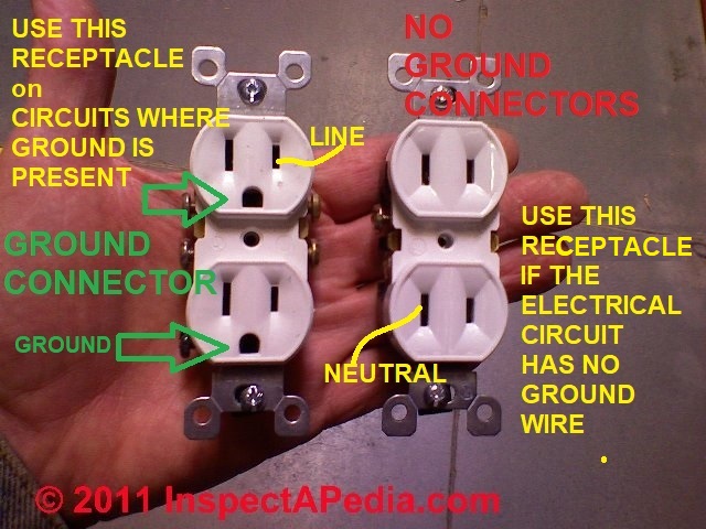
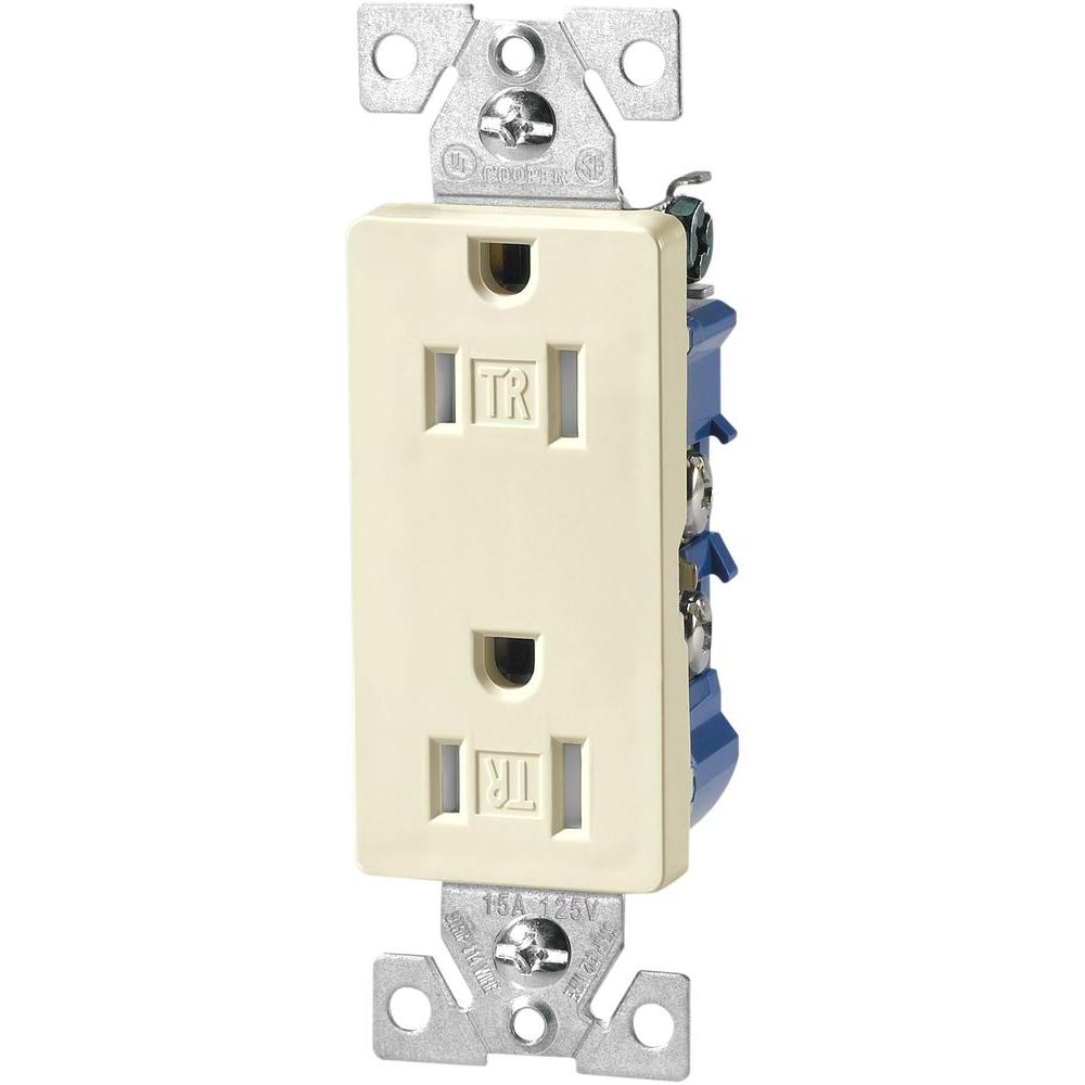
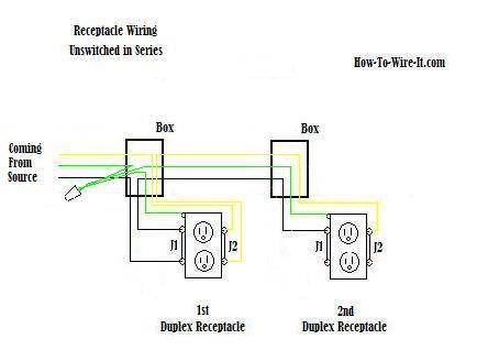
Wiring two outlets side by side. No linesman pliers no problem. This wiring is commonly used in a 20 amp kitchen circuit where two appliance feeds are needed such as for a refrigerator and a microwave in the same location. Tighten the screw firmly. You may have to splice these ground conductors together and add a small piece of wire to the splice. Electrical outlet receptacles come with two means of making the wire connections. Either method can be used to make the circuit wire connections.
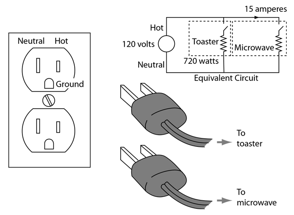
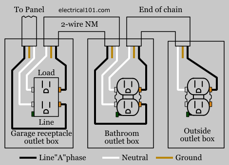
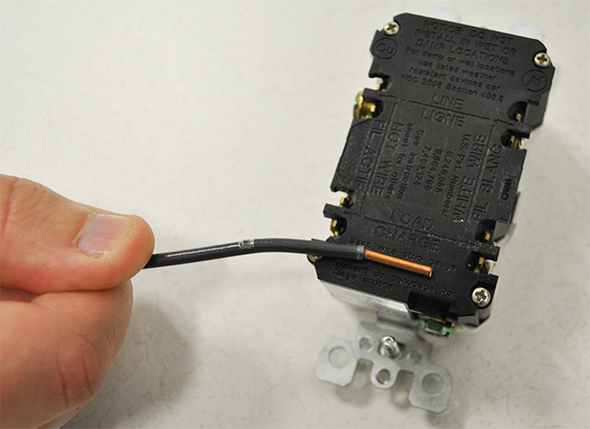
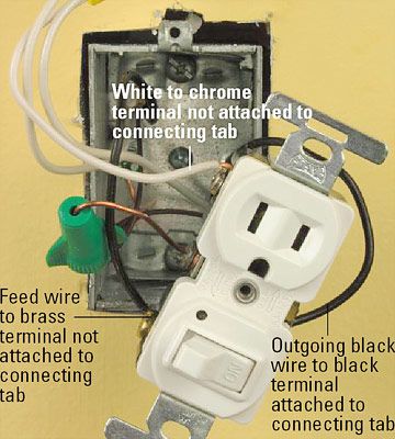
Wiring a combo switch outlet. Take any remaining white wires and attach them on the load side silver screw. Here 3 wire cable is run from a double pole circuit breaker providing an independent 120 volts to two sets of multiple outlets. Cut two lengths of black wire and two lengths of bare copper wire about 6 inches long. If you plan on using common duplex receptacles the devices with 2 outlets on a single frame you will need to break off a little jumper tab that ties the wire contact plate under the terminal screws together on the hot side to isolate the switched receptacle from the unswitched. Properly wiring two duplex receptacles side by side.
Form a c shaped loop in one end of the black wires and hook it in a clockwise direction around the bottom screw terminal on the side of the switch. Electrical wiring for a switch outlet combination. Take any remaining black wires and attach them on the load side brass screw. Strip about 34 inch of insulation from one end of each black wire. Connect the white wire to the bottom silver lug in the same way. Start by wiring the first receptacle to the live circuit cable.
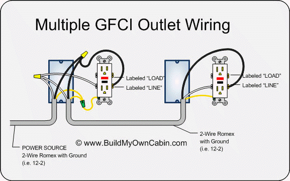
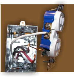
Wiring two outlets in one box in this diagram two duplex receptacle outlets are installed in the same box and wired separately to the source using pigtails spliced to connect the terminals of each one. Pull the cable through a hole in the back of the electrical box separate the wires and strip an inch of insulation off the end of each one. They have push fit openings on the back of the receptacle as well as screw terminals on the sides of the receptacle body. Wiring diagram for dual outlets. With each outlet connected by its own pigtail wire if one fails because of physical damage the other wont be affected and should still work. Take the bare or green wire and attach it to the green screw on the gfci outlet.
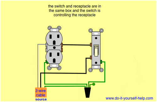
The neutral wire from the circuit is shared by both sets. Using the pigtail method. Basic tools still get the job done with proper methods and techniques. How to install electrical outlet and switch combo wiring in most cases the primary power source is shared between the switch and the outlet either with a wire jumper or the bridge or tab that is located on the side of the combo switch and outlet. Of insulation off the ends and connect the wires from the new cable to the existing bundles white to white black to black ground to ground.


/cdn.vox-cdn.com/uploads/chorus_image/image/66475077/electrical-upgrades-3-x.0.0.jpg)
