It is often required to switch electrical appliances from a distance without being a direct line of sight between the transmitter and receiver. Remote controlled switch for home appliance.
Ir Infrared Remote Control Switch Circuit And Applications
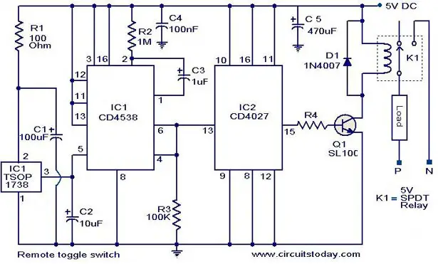
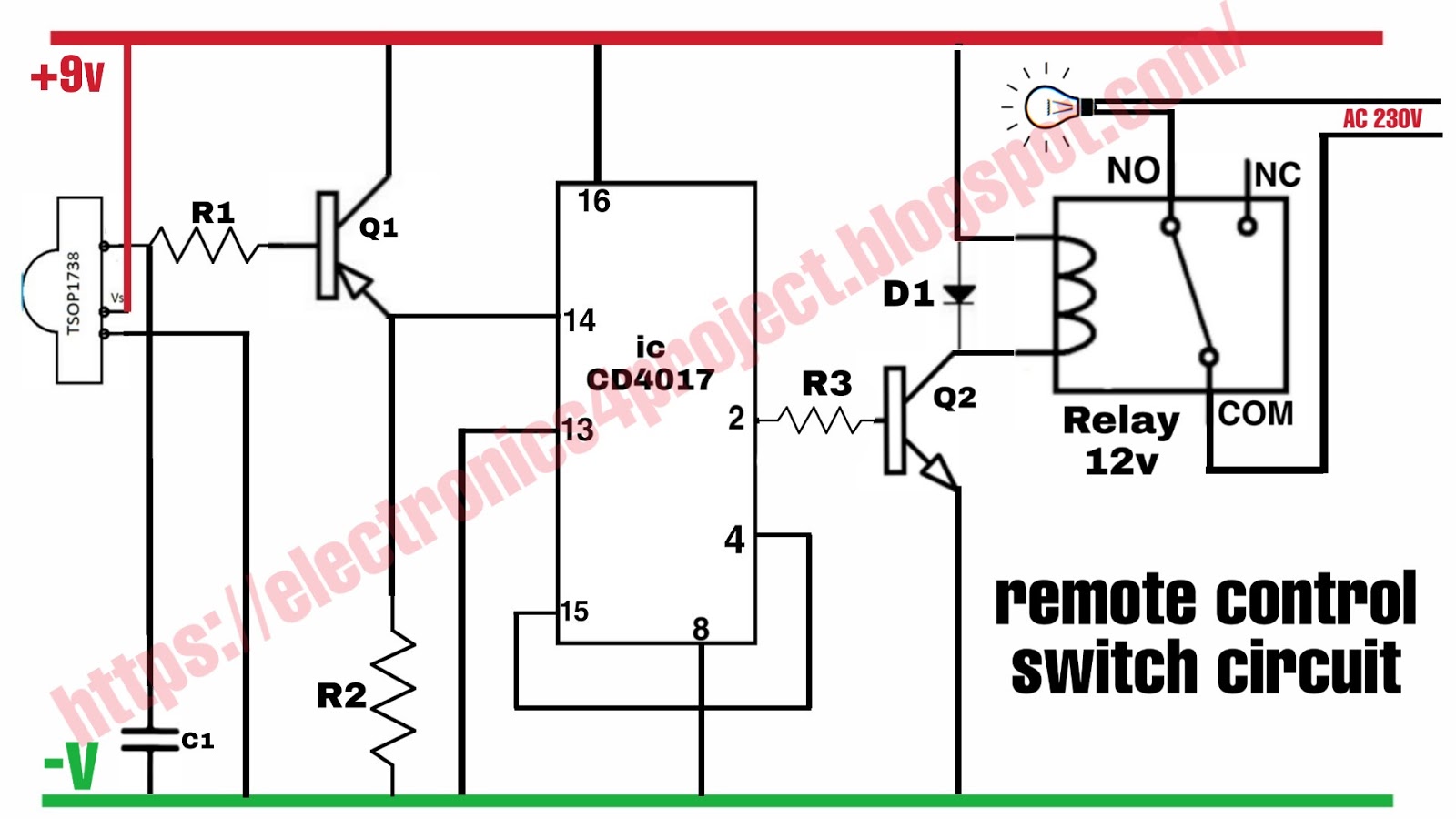
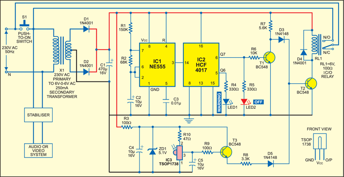
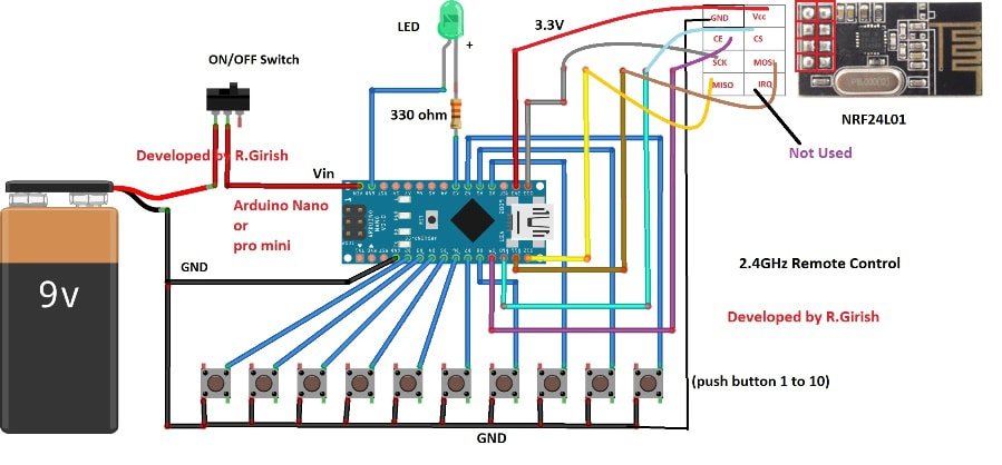
Remote switch circuit diagram. These devices are designed to provide a high level of security. Remote controlled on off switch circuit. Circuit design of remote controlled light switch. We uses normal switch in our daily life and after a long time used to these swithing system we can no more interested in that. We have used ic 4017 to convert it into a push on push off switch. This remote gives approximately 150 meter coverage by extending the ariel wire it can be increased up to 200 meters.
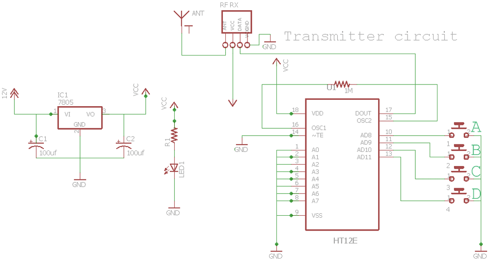
Circuit diagram of infrared remote control switch. The main components of the project are ic cd4017 and tsop 1738 ir receiver. Receiver circuit first we go with transmitter circuit design. This current is given to the inverting input of 3130 ic which will get triggered by this current and give amplified output. Remote controlled switch circuit diagram notes. Remote controlled switch this is the very simple circuit diagram of ir remote control switch.
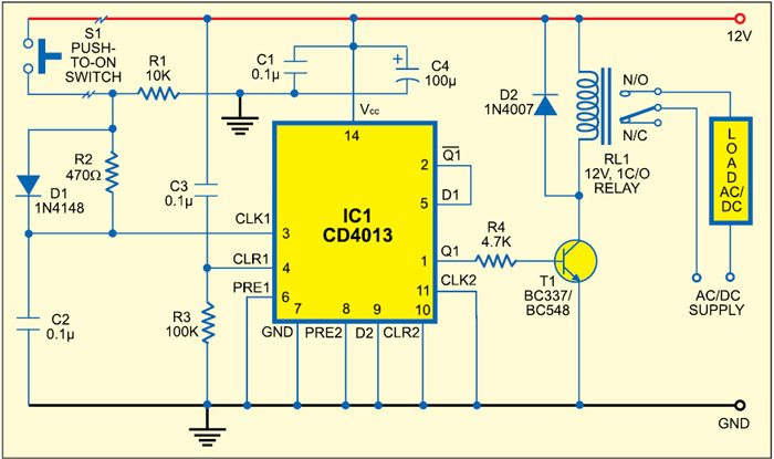
The whole project contains two parts which is an fm transmitter and a rf receiver. A single channel relay board is sufficient. The circuit works by pressing any key on the remote it can also operated manually by pressing switch s1 to on state. You can on or off any appliance by this circuit ie fan light etcthis is works upto 5 10 m lenght from remote. As you may well know an rf based wireless remote control system rf transmitter rf receiver can be used to control an output load from a remote place. In the receiver section there are 3 photodiodes which will detect the infrared signals from the receiver and produce leakage current to the capacitor c1.
Receiver circuit is connected to ac appliance via relay so that we can control the light remotely. A relay switch is used at the output of the circuit which can be connected with the appliances to make them switch onoff. Alternatively the relay circuit can be built as per the circuit diagram. Here is the circuit diagram of an fm remote encoderdecoder using the ics rf600e and rf600d. The output of the ir receiver is a decoded output of the signal from remote control. For good results use a good quality fm transmitter with the circuit.
The circuit has also a good range of upto 20 meters. In this remote controlled switch circuit we are using tv remote to onoff the ac light by pressing any button of remote and using the tsop1738 at receiver end. Before wiring the circuit make sure that the carrier frequency of the tv remote you have is 38 khzfor that wire the sensor part only point your remote to the tsop1738 and press any switchif out put of tsop1738 goes low then ok your remote is of 38khz typenothing to worry almost all tv. This project has two stages that is 1. This circuit has three stages they are.
Gallery of Remote Switch Circuit Diagram